How to Use 6 channel relay module: Examples, Pinouts, and Specs
Introduction
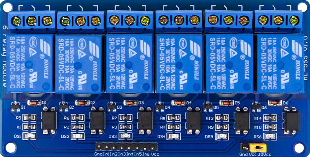
The 6 channel relay module is an electronic component designed to control multiple high-voltage devices using low-voltage signals. Each of the six relays on the module acts as an electrically operated switch, allowing you to control high-power devices such as lights, fans, motors, and appliances with ease. This module is widely used in home automation, industrial control systems, and IoT projects.
Explore Projects Built with 6 channel relay module


Explore Projects Built with 6 channel relay module
Common Applications and Use Cases
- Home automation systems (e.g., controlling lights, fans, and appliances)
- Industrial equipment control
- Robotics and motor control
- IoT projects for remote device management
- Smart agriculture systems (e.g., irrigation pumps)
Technical Specifications
Key Technical Details
- Operating Voltage: 5V DC
- Trigger Voltage: 3.3V to 5V (compatible with most microcontrollers)
- Relay Type: SPDT (Single Pole Double Throw)
- Maximum Load (per relay):
- AC: 250V at 10A
- DC: 30V at 10A
- Optocoupler Isolation: Yes (provides electrical isolation between control and load sides)
- Indicator LEDs: One LED per relay to indicate its state (ON/OFF)
- Dimensions: Approximately 140mm x 50mm x 20mm
Pin Configuration and Descriptions
The 6 channel relay module has two main sections: the control pins and the load terminals.
Control Pins
| Pin Name | Description |
|---|---|
| VCC | Power supply for the module (5V DC). |
| GND | Ground connection. |
| IN1 to IN6 | Control pins for each relay. A LOW signal activates the corresponding relay. |
Load Terminals (for each relay)
| Terminal | Description |
|---|---|
| COM | Common terminal for the relay. |
| NO | Normally Open terminal. Connect here if the device should be OFF by default. |
| NC | Normally Closed terminal. Connect here if the device should be ON by default. |
Usage Instructions
How to Use the Component in a Circuit
- Power the Module: Connect the VCC pin to a 5V DC power source and the GND pin to ground.
- Connect the Control Pins: Connect the IN1 to IN6 pins to the digital output pins of a microcontroller (e.g., Arduino, Raspberry Pi).
- Connect the Load:
- Identify the device you want to control (e.g., a light bulb or motor).
- Connect one terminal of the device to the relay's COM terminal.
- Connect the other terminal to either the NO or NC terminal, depending on whether the device should be OFF or ON by default.
- Ensure the load's power source is properly connected to the relay circuit.
- Control the Relays: Send a LOW signal (0V) to the corresponding IN pin to activate the relay and switch the load.
Important Considerations and Best Practices
- Electrical Isolation: The module includes optocouplers for isolation, but ensure proper grounding to avoid electrical noise.
- Power Supply: Use a stable 5V DC power source to prevent erratic relay behavior.
- Load Ratings: Do not exceed the maximum load ratings (250V AC/10A or 30V DC/10A) to avoid damage.
- Flyback Diodes: If controlling inductive loads (e.g., motors), use flyback diodes to protect the relays from voltage spikes.
- Microcontroller Compatibility: Ensure the control signals are within the 3.3V to 5V range.
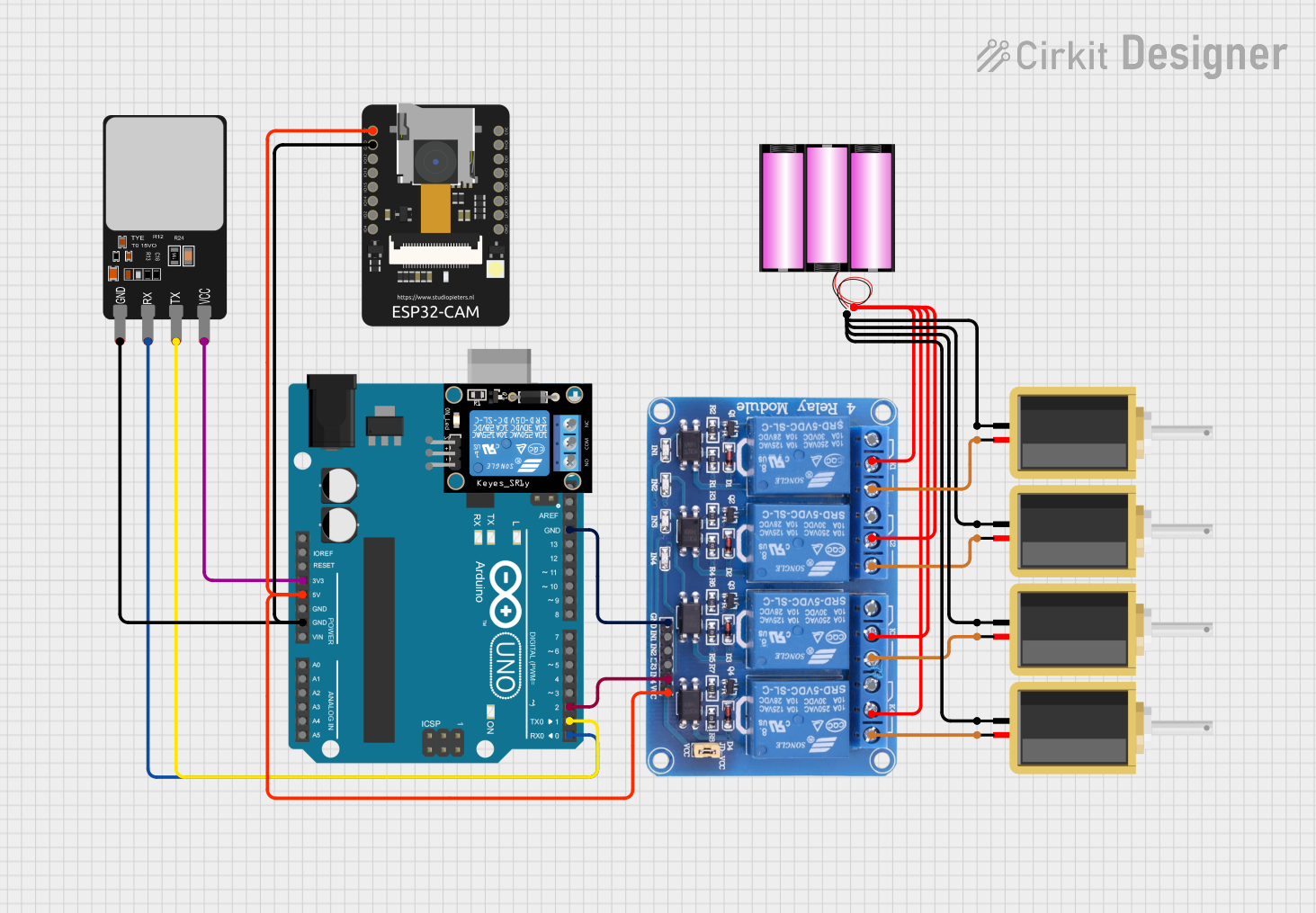
Example: Connecting to an Arduino UNO
Below is an example of how to control the 6 channel relay module using an Arduino UNO.
Circuit Connections
- Connect the module's VCC to the Arduino's 5V pin.
- Connect the module's GND to the Arduino's GND pin.
- Connect IN1 to IN6 to Arduino digital pins 2 to 7, respectively.
- Connect a load (e.g., a light bulb) to one of the relay terminals (COM and NO/NC).
Arduino Code
// Example code to control a 6 channel relay module with Arduino UNO

// Define the relay control pins
#define RELAY1 2
#define RELAY2 3
#define RELAY3 4
#define RELAY4 5
#define RELAY5 6
#define RELAY6 7

void setup() {
  // Set relay pins as outputs
  pinMode(RELAY1, OUTPUT);
  pinMode(RELAY2, OUTPUT);
  pinMode(RELAY3, OUTPUT);
  pinMode(RELAY4, OUTPUT);
  pinMode(RELAY5, OUTPUT);
  pinMode(RELAY6, OUTPUT);

  // Initialize all relays to OFF state
  digitalWrite(RELAY1, HIGH); // HIGH = relay OFF
  digitalWrite(RELAY2, HIGH);
  digitalWrite(RELAY3, HIGH);
  digitalWrite(RELAY4, HIGH);
  digitalWrite(RELAY5, HIGH);
  digitalWrite(RELAY6, HIGH);
}

void loop() {
  // Example: Turn relays ON and OFF sequentially
  digitalWrite(RELAY1, LOW); // LOW = relay ON
  delay(1000);               // Wait 1 second
  digitalWrite(RELAY1, HIGH);

  digitalWrite(RELAY2, LOW);
  delay(1000);
  digitalWrite(RELAY2, HIGH);

  digitalWrite(RELAY3, LOW);
  delay(1000);
  digitalWrite(RELAY3, HIGH);

  digitalWrite(RELAY4, LOW);
  delay(1000);
  digitalWrite(RELAY4, HIGH);

  digitalWrite(RELAY5, LOW);
  delay(1000);
  digitalWrite(RELAY5, HIGH);

  digitalWrite(RELAY6, LOW);
  delay(1000);
  digitalWrite(RELAY6, HIGH);
}
Troubleshooting and FAQs
Common Issues and Solutions
Relays Not Activating:
- Ensure the module is powered with a stable 5V DC supply.
- Verify that the control signals from the microcontroller are within the 3.3V to 5V range.
- Check the wiring connections for loose or incorrect connections.
Erratic Relay Behavior:
- Use a separate power supply for the relay module if the microcontroller's power source is insufficient.
- Ensure proper grounding between the relay module and the microcontroller.
Load Not Switching:
- Verify that the load is connected to the correct relay terminals (COM and NO/NC).
- Check the load's power source and ensure it is properly connected.
LED Indicators Not Working:
- Check the module's VCC and GND connections.
- Ensure the relays are receiving the correct control signals.
FAQs
Q: Can I use the module with a 3.3V microcontroller like ESP32?
A: Yes, the module is compatible with 3.3V control signals, but ensure the power supply to the module is 5V.
Q: Can I control AC and DC loads simultaneously?
A: Yes, as long as each relay's load does not exceed the specified ratings.
Q: Do I need external components to use the module?
A: No additional components are required for basic operation, but flyback diodes are recommended for inductive loads.