How to Use GM803 1D/2D Barcode Reader Module CMOS Scanner TTL/USB: Examples, Pinouts, and Specs
Introduction
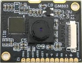
The GM803 is a versatile barcode scanner module designed to read both 1D and 2D barcodes with high efficiency. Utilizing advanced CMOS imaging technology, it ensures accurate and fast barcode decoding. The module supports both TTL and USB interfaces, making it easy to integrate into a wide range of electronic systems, including embedded devices, kiosks, and point-of-sale (POS) systems.
Explore Projects Built with GM803 1D/2D Barcode Reader Module CMOS Scanner TTL/USB
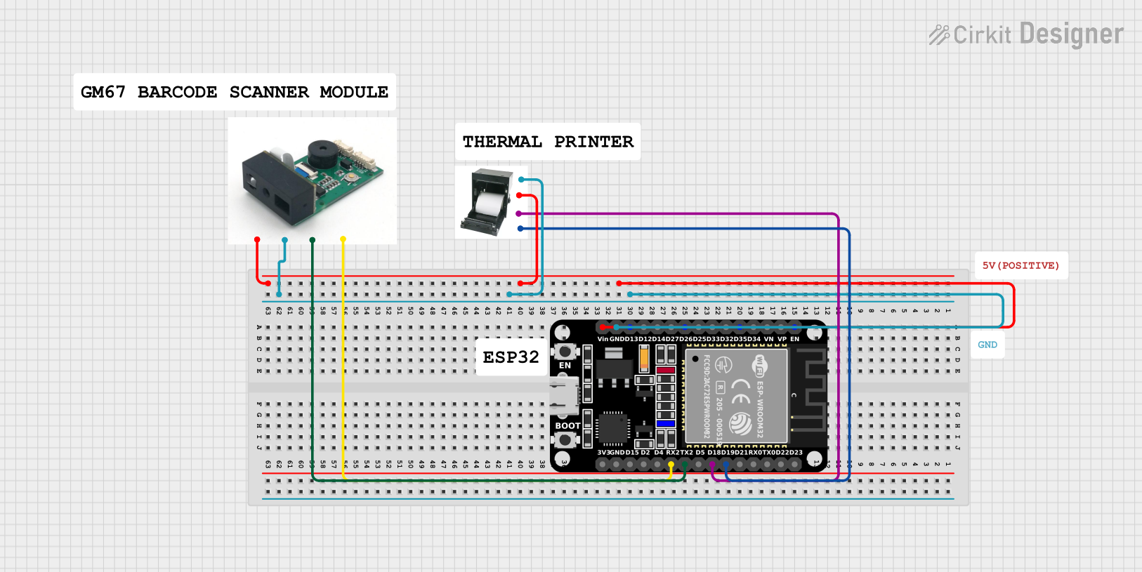


Explore Projects Built with GM803 1D/2D Barcode Reader Module CMOS Scanner TTL/USB
Common Applications and Use Cases
- Retail and POS systems for inventory management
- Embedded systems in kiosks and vending machines
- Access control and ticketing systems
- Warehouse and logistics for barcode scanning
- Industrial automation requiring barcode identification
Technical Specifications
Key Technical Details
| Parameter | Specification |
|---|---|
| Barcode Types Supported | 1D (e.g., Code 128, EAN-13) and 2D (e.g., QR Code, Data Matrix) |
| Sensor Type | CMOS |
| Interface Options | TTL, USB |
| Operating Voltage | 3.3V to 5V |
| Current Consumption | < 120mA |
| Scanning Speed | Up to 300 scans per second |
| Resolution | 640 x 480 pixels |
| Operating Temperature | -20°C to 60°C |
| Dimensions | 21mm x 15mm x 10mm |
Pin Configuration and Descriptions
TTL Interface Pinout
| Pin Number | Pin Name | Description |
|---|---|---|
| 1 | VCC | Power supply input (3.3V to 5V) |
| 2 | GND | Ground |
| 3 | TXD | Transmit data (TTL level) |
| 4 | RXD | Receive data (TTL level) |
| 5 | Trigger | External trigger input (active low) |
| 6 | Beeper | Beeper control output |
USB Interface Pinout
| Pin Number | Pin Name | Description |
|---|---|---|
| 1 | VBUS | USB power supply (5V) |
| 2 | D- | USB data negative |
| 3 | D+ | USB data positive |
| 4 | GND | Ground |
Usage Instructions
How to Use the GM803 in a Circuit
- Power Supply: Connect the VCC pin to a 3.3V or 5V power source and the GND pin to ground.
- Interface Selection:
- For TTL communication, connect the TXD and RXD pins to the corresponding UART pins of your microcontroller.
- For USB communication, connect the USB pins (VBUS, D-, D+, GND) to a USB host device.
- Triggering: Use the Trigger pin to initiate a scan. Pull the pin low to activate the scanner.
- Data Output: The scanned barcode data will be transmitted via the selected interface (TTL or USB).
Important Considerations and Best Practices
- Ensure the power supply voltage is within the specified range (3.3V to 5V) to avoid damage to the module.
- Use proper pull-up resistors for the TTL interface if required by your microcontroller.
- Avoid exposing the module to direct sunlight or reflective surfaces, as this may interfere with scanning performance.
- For USB communication, ensure the host device supports USB HID or virtual COM port functionality.
Example: Connecting to an Arduino UNO (TTL Interface)
Below is an example of how to connect and use the GM803 with an Arduino UNO via the TTL interface.
Wiring Diagram
| GM803 Pin | Arduino UNO Pin |
|---|---|
| VCC | 5V |
| GND | GND |
| TXD | RX (Pin 0) |
| RXD | TX (Pin 1) |
| Trigger | Digital Pin 2 |
Arduino Code Example
#include <SoftwareSerial.h>

// Define RX and TX pins for the GM803 module
SoftwareSerial barcodeScanner(10, 11); // RX = Pin 10, TX = Pin 11

// Define the trigger pin
const int triggerPin = 2;

void setup() {
  // Initialize serial communication
  Serial.begin(9600); // For debugging
  barcodeScanner.begin(9600); // For GM803 communication

  // Configure the trigger pin
  pinMode(triggerPin, OUTPUT);
  digitalWrite(triggerPin, HIGH); // Set trigger pin to inactive state

  Serial.println("GM803 Barcode Scanner Initialized");
}

void loop() {
  // Trigger a scan
  digitalWrite(triggerPin, LOW); // Activate the scanner
  delay(100); // Wait for the scan to complete
  digitalWrite(triggerPin, HIGH); // Deactivate the scanner

  // Check if data is available from the scanner
  if (barcodeScanner.available()) {
    String barcodeData = "";
    while (barcodeScanner.available()) {
      char c = barcodeScanner.read();
      barcodeData += c;
    }
    Serial.println("Scanned Barcode: " + barcodeData);
  }

  delay(1000); // Wait before the next scan
}
Troubleshooting and FAQs
Common Issues and Solutions
No Data Output from the Scanner
- Cause: Incorrect wiring or interface selection.
- Solution: Double-check the connections and ensure the correct interface (TTL or USB) is being used.
Scanner Does Not Trigger
- Cause: Trigger pin not properly configured.
- Solution: Verify the trigger pin wiring and ensure it is pulled low to activate the scanner.
Unreadable or Inaccurate Scans
- Cause: Poor lighting conditions or damaged barcodes.
- Solution: Ensure adequate lighting and use undamaged barcodes for scanning.
Module Overheating
- Cause: Excessive voltage or prolonged operation.
- Solution: Ensure the power supply voltage is within the specified range and allow the module to cool down if used continuously.
FAQs
Can the GM803 read barcodes on screens?
- Yes, the GM803 can read barcodes displayed on screens, such as smartphones or tablets, provided the screen brightness is sufficient.
What is the maximum scanning distance?
- The maximum scanning distance depends on the barcode size and type but typically ranges from 5cm to 30cm.
Is the GM803 compatible with Raspberry Pi?
- Yes, the GM803 can be connected to a Raspberry Pi via the USB or TTL interface.
Does the module require additional drivers for USB communication?
- The GM803 is typically recognized as a USB HID device or virtual COM port, and most operating systems will automatically install the necessary drivers.