How to Use Motor Controller: Examples, Pinouts, and Specs
Introduction
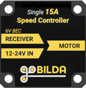
The GoBilda Motor Controller (Part ID: 3105-0101-0015) is a versatile device designed to regulate the speed, direction, and torque of electric motors. By controlling the power supplied to the motor, it enables precise motor operation in a variety of applications. This motor controller is compatible with brushed DC motors and is ideal for robotics, automation systems, and other motor-driven projects.
Explore Projects Built with Motor Controller

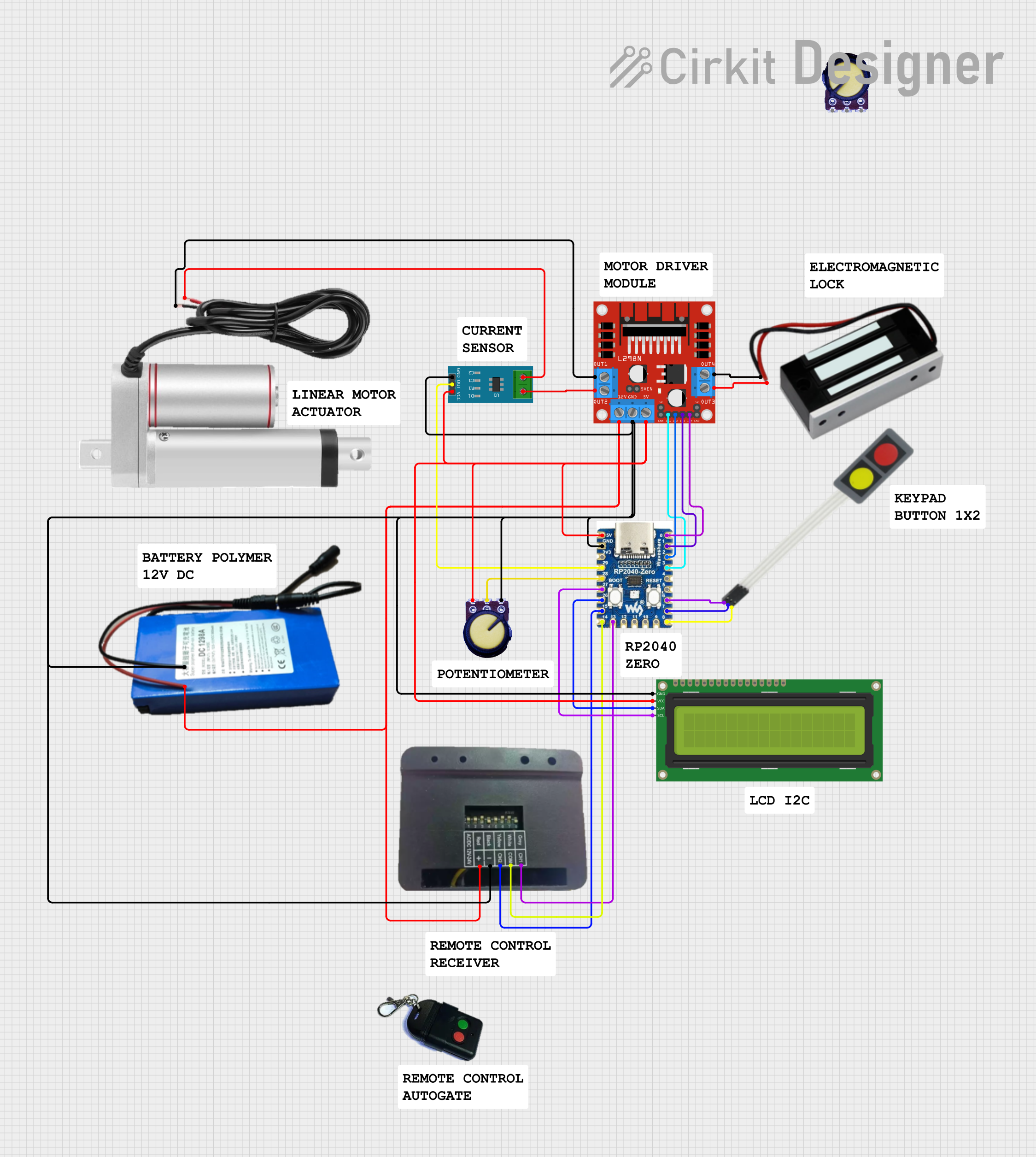
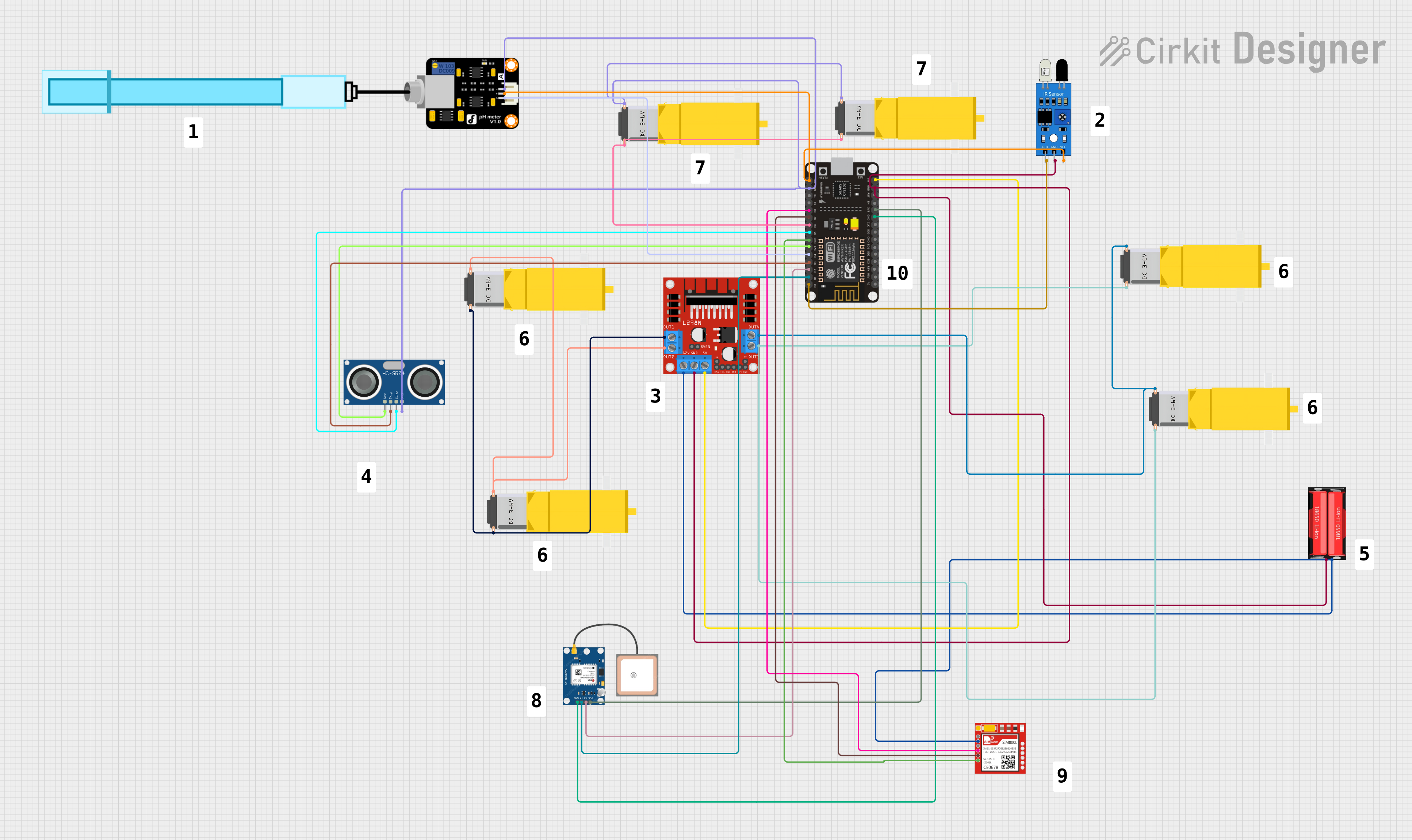
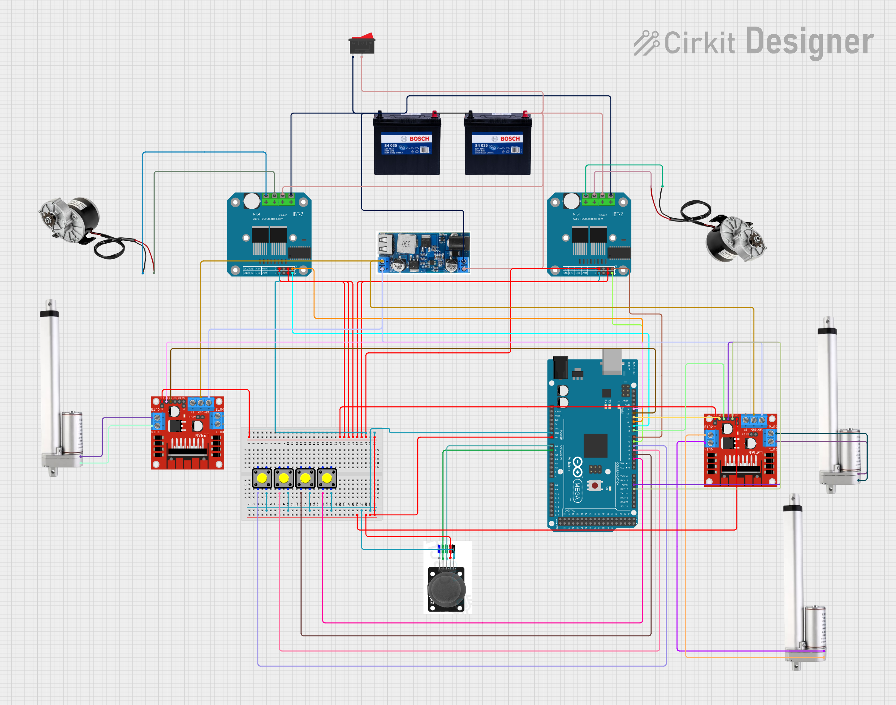
Explore Projects Built with Motor Controller
Common Applications and Use Cases
- Robotics: Controlling drive motors, robotic arms, and other actuators.
- Automation: Regulating conveyor belts, pumps, and industrial machinery.
- DIY Projects: Building motorized vehicles, drones, or other hobbyist creations.
- Educational Use: Teaching motor control concepts in engineering and electronics courses.
Technical Specifications
The following table outlines the key technical details of the GoBilda Motor Controller:
| Specification | Value |
|---|---|
| Manufacturer | GoBilda |
| Part ID | 3105-0101-0015 |
| Input Voltage Range | 6V to 24V DC |
| Continuous Current Rating | 15A |
| Peak Current Rating | 30A (for up to 10 seconds) |
| Control Signal Type | PWM (Pulse Width Modulation) |
| PWM Frequency Range | 1 kHz to 20 kHz |
| Motor Type Compatibility | Brushed DC Motors |
| Direction Control | Forward/Reverse |
| Speed Control | 0% to 100% duty cycle |
| Operating Temperature | -20°C to 60°C |
| Dimensions | 50mm x 40mm x 15mm |
| Weight | 35g |
Pin Configuration and Descriptions
The motor controller has the following pin layout:
| Pin Name | Type | Description |
|---|---|---|
| VIN | Power Input | Connect to the positive terminal of the power supply (6V to 24V DC). |
| GND | Power Ground | Connect to the negative terminal of the power supply. |
| M+ | Motor Output | Connect to the positive terminal of the brushed DC motor. |
| M- | Motor Output | Connect to the negative terminal of the brushed DC motor. |
| PWM | Control Input | Accepts a PWM signal to control motor speed (0% to 100% duty cycle). |
| DIR | Control Input | Logic-level input to control motor direction (HIGH for forward, LOW for reverse). |
| EN | Control Input | Enable pin; set HIGH to enable the motor controller, LOW to disable it. |
Usage Instructions
How to Use the Component in a Circuit
- Power Supply Connection: Connect the VIN and GND pins to a DC power supply within the specified voltage range (6V to 24V).
- Motor Connection: Attach the motor terminals to the M+ and M- pins. Ensure proper polarity for correct operation.
- Control Signal:
- Use a microcontroller (e.g., Arduino UNO) to generate a PWM signal for speed control.
- Use the DIR pin to set the motor's direction (HIGH for forward, LOW for reverse).
- Use the EN pin to enable or disable the motor controller.
Important Considerations and Best Practices
- Current Rating: Ensure the motor's current draw does not exceed the controller's continuous current rating (15A). For brief surges, the peak current rating (30A) must not be exceeded for more than 10 seconds.
- Heat Dissipation: If operating near the maximum current rating, consider adding a heatsink or active cooling to prevent overheating.
- PWM Frequency: Use a PWM frequency within the specified range (1 kHz to 20 kHz) for optimal performance.
- Reverse Polarity Protection: Double-check connections to avoid damage caused by reverse polarity.
Example: Using the Motor Controller with an Arduino UNO
Below is an example Arduino sketch to control motor speed and direction using the GoBilda Motor Controller:
// Define pin connections
const int pwmPin = 9;  // PWM signal pin connected to the motor controller's PWM pin
const int dirPin = 8;  // Direction control pin connected to the DIR pin
const int enPin = 7;   // Enable pin connected to the EN pin

void setup() {
  // Set pin modes
  pinMode(pwmPin, OUTPUT);
  pinMode(dirPin, OUTPUT);
  pinMode(enPin, OUTPUT);

  // Enable the motor controller
  digitalWrite(enPin, HIGH);
}

void loop() {
  // Set motor direction to forward
  digitalWrite(dirPin, HIGH);

  // Gradually increase motor speed
  for (int speed = 0; speed <= 255; speed++) {
    analogWrite(pwmPin, speed); // Write PWM signal to control speed
    delay(20);                  // Small delay for smooth acceleration
  }

  delay(1000); // Run at full speed for 1 second

  // Set motor direction to reverse
  digitalWrite(dirPin, LOW);

  // Gradually decrease motor speed
  for (int speed = 255; speed >= 0; speed--) {
    analogWrite(pwmPin, speed); // Write PWM signal to control speed
    delay(20);                  // Small delay for smooth deceleration
  }

  delay(1000); // Pause before repeating the loop
}
Troubleshooting and FAQs
Common Issues and Solutions
Motor Not Running:
- Ensure the EN pin is set HIGH to enable the motor controller.
- Verify that the power supply voltage is within the specified range (6V to 24V).
- Check all connections for loose wires or incorrect polarity.
Motor Running in the Wrong Direction:
- Verify the logic level on the DIR pin. Set it HIGH for forward and LOW for reverse.
- Check the motor connections to the M+ and M- pins.
Overheating:
- Ensure the motor's current draw does not exceed the controller's continuous current rating.
- Add a heatsink or active cooling if operating near the maximum current rating.
PWM Signal Not Working:
- Confirm that the PWM signal frequency is within the range of 1 kHz to 20 kHz.
- Check the microcontroller's PWM pin configuration and ensure it is outputting a signal.
FAQs
Can this motor controller be used with brushless motors? No, this motor controller is designed specifically for brushed DC motors.
What happens if the input voltage exceeds 24V? Exceeding the maximum input voltage may damage the motor controller. Always use a power supply within the specified range.
Is reverse polarity protection included? No, the motor controller does not have built-in reverse polarity protection. Double-check connections before powering the circuit.
Can I use this motor controller with a battery? Yes, as long as the battery voltage is within the 6V to 24V range and can supply sufficient current for the motor.