How to Use L298N: Examples, Pinouts, and Specs
Introduction
The L298N is a dual H-bridge motor driver IC designed to control the direction and speed of DC motors and stepper motors. It is widely used in robotics, automation, and other motor control applications due to its ability to drive two motors simultaneously. With a current handling capacity of up to 2A per channel and a wide operating voltage range, the L298N is a versatile and reliable choice for motor control in various projects.
Explore Projects Built with L298N
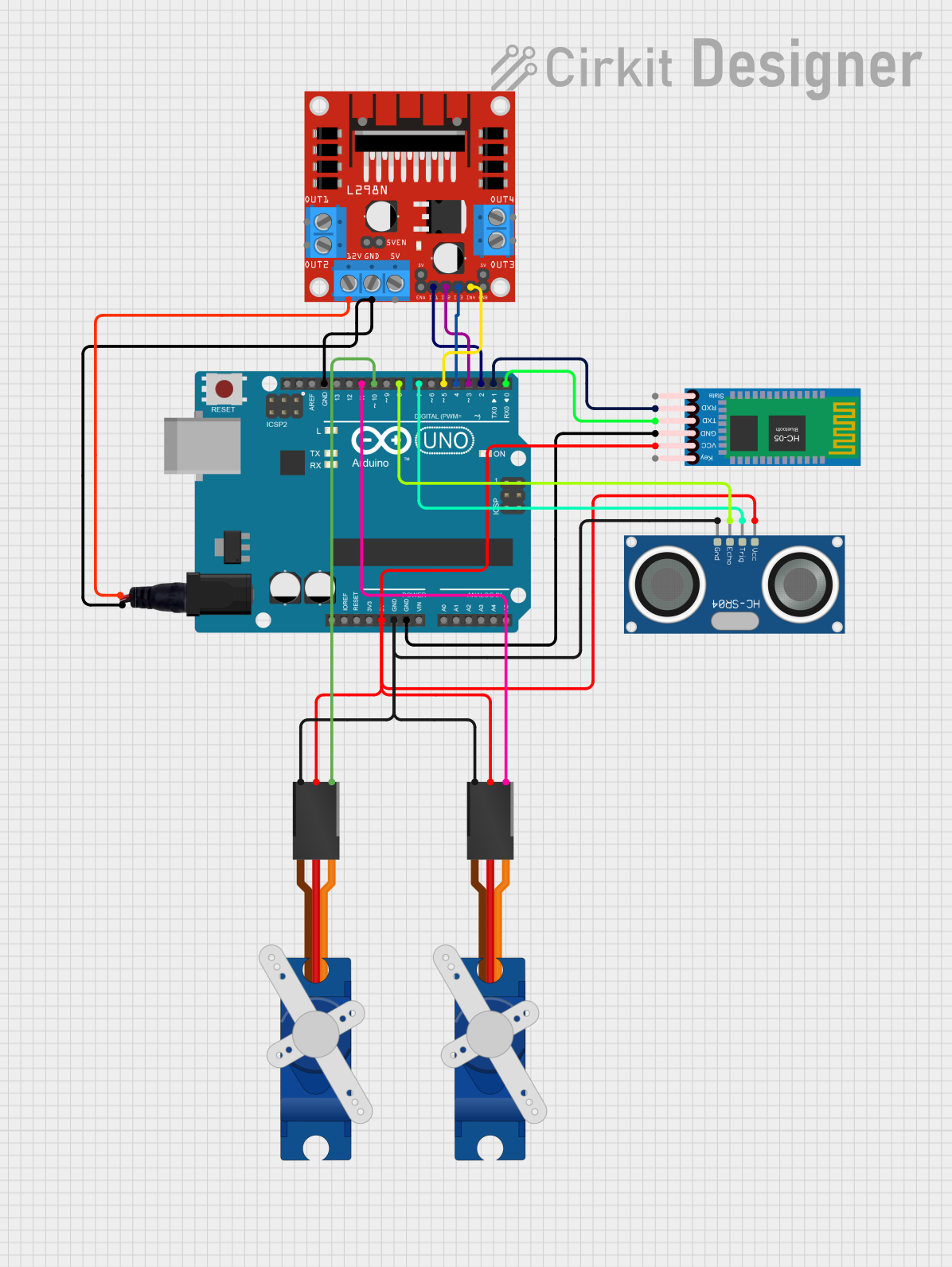
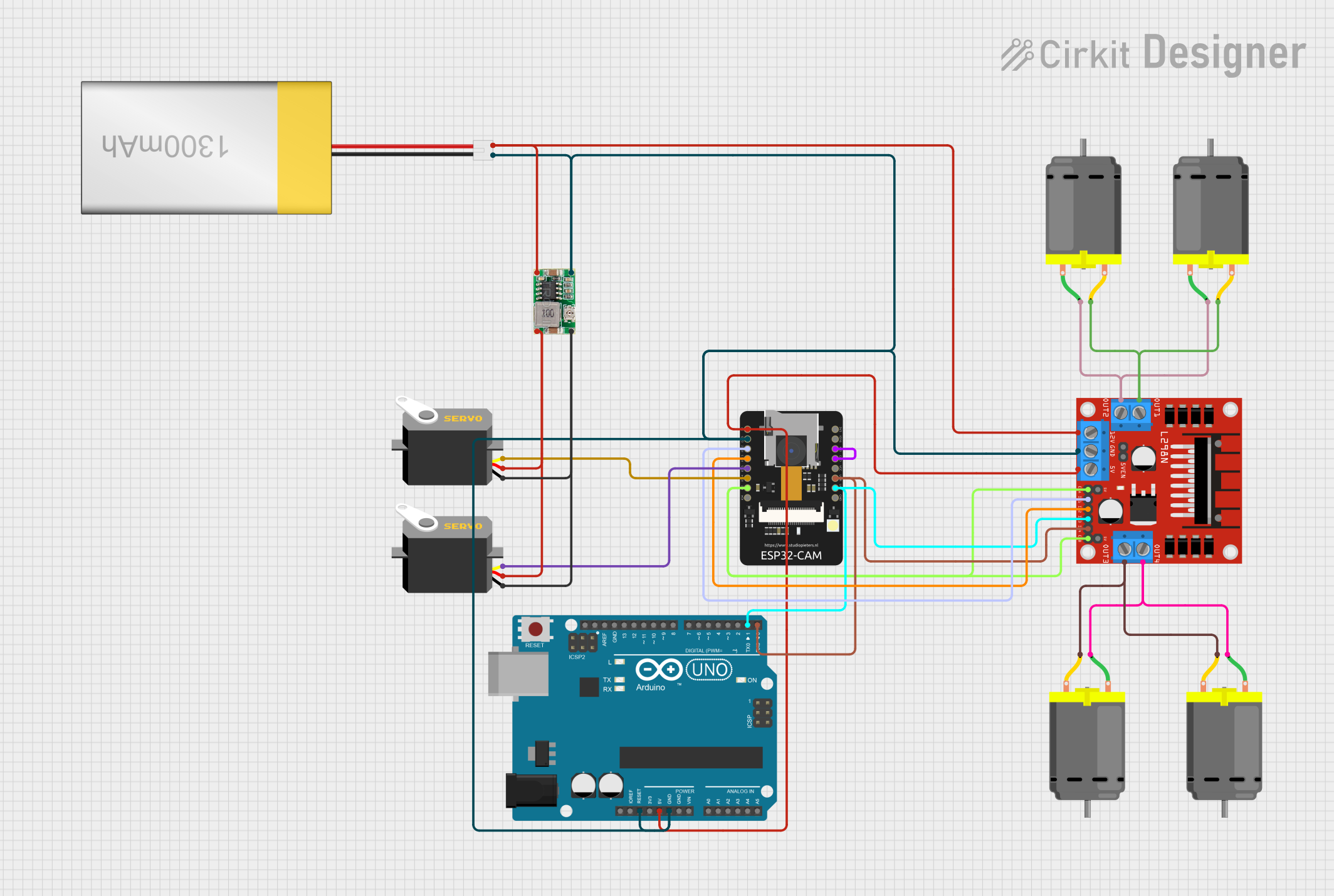
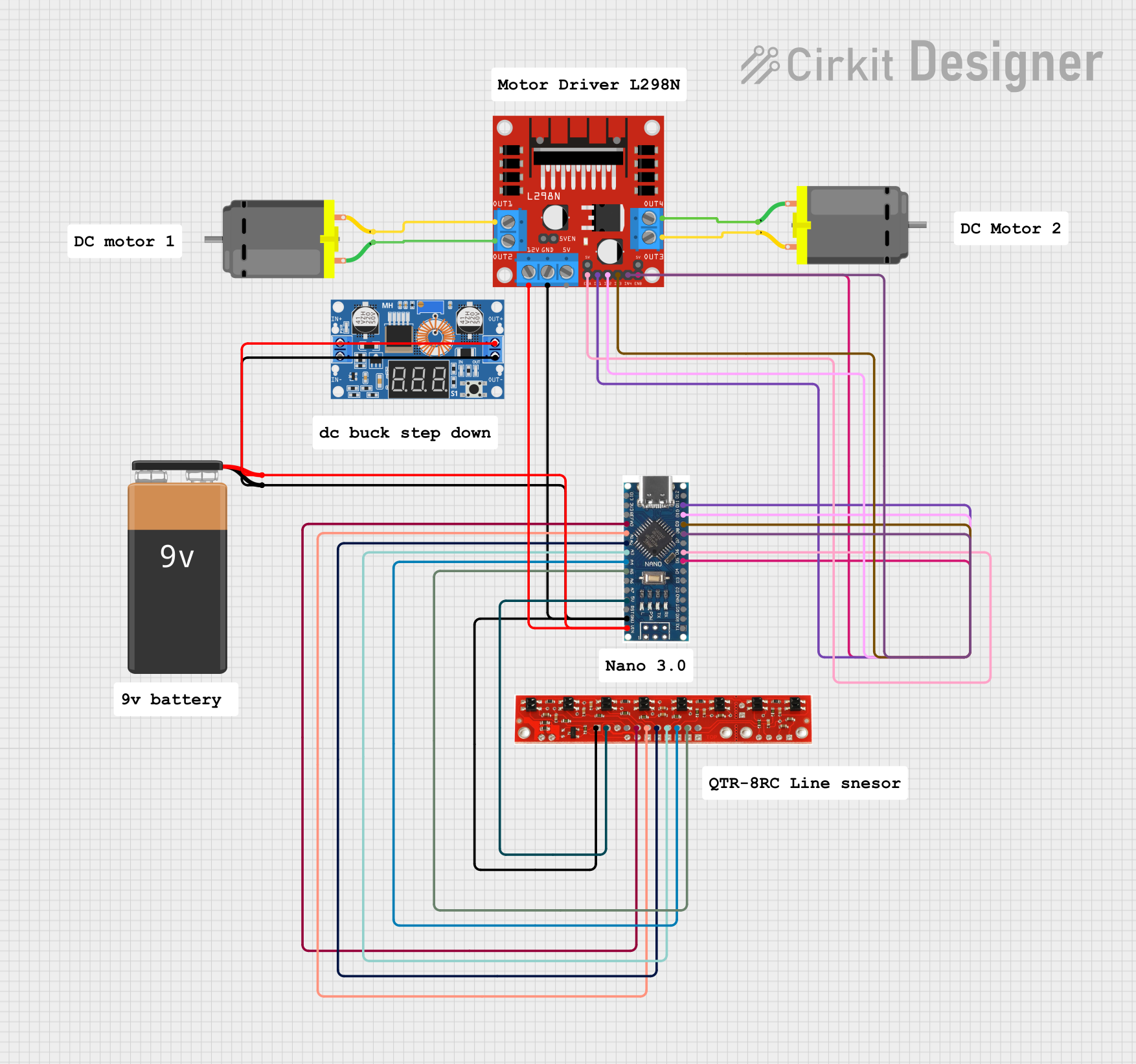

Explore Projects Built with L298N
Common Applications
- Robotics and automation systems
- Motorized vehicles and robotic arms
- CNC machines and 3D printers
- Conveyor belts and industrial equipment
- Educational projects involving motor control
Technical Specifications
Key Technical Details
- Operating Voltage (Vcc): 5V to 46V
- Logic Voltage (Vss): 5V
- Output Current (per channel): Up to 2A
- Maximum Power Dissipation: 25W
- Control Logic Levels: High (5V), Low (0V)
- Number of Channels: 2 (dual H-bridge)
- Thermal Protection: Yes
- Dimensions (for L298N module): ~43mm x 43mm x 27mm
Pin Configuration and Descriptions
The L298N IC is often used in a module form, which includes additional components like a voltage regulator and terminal blocks for easier connections. Below is the pin configuration for the L298N module:
| Pin Name | Type | Description |
|---|---|---|
| IN1 | Input | Controls the direction of Motor A (High/Low). |
| IN2 | Input | Controls the direction of Motor A (High/Low). |
| IN3 | Input | Controls the direction of Motor B (High/Low). |
| IN4 | Input | Controls the direction of Motor B (High/Low). |
| ENA | Input (PWM) | Enables and controls the speed of Motor A (PWM signal). |
| ENB | Input (PWM) | Enables and controls the speed of Motor B (PWM signal). |
| OUT1 | Output | Connects to one terminal of Motor A. |
| OUT2 | Output | Connects to the other terminal of Motor A. |
| OUT3 | Output | Connects to one terminal of Motor B. |
| OUT4 | Output | Connects to the other terminal of Motor B. |
| Vcc | Power Input | Motor power supply (5V to 46V). |
| GND | Power Ground | Ground connection for the circuit. |
| 5V | Power Output | Provides 5V output (used when the onboard regulator is active). |
Note: The onboard voltage regulator allows the module to provide 5V output when the input voltage (Vcc) is greater than 7V. If using a 5V power source, the jumper on the module should be removed.
Usage Instructions
How to Use the L298N in a Circuit
Power Connections:
- Connect the motor power supply to the
Vccterminal (5V to 46V). - Connect the ground of the power supply to the
GNDterminal. - If using a logic voltage of 5V, ensure the onboard regulator is configured correctly.
- Connect the motor power supply to the
Motor Connections:
- Connect the terminals of Motor A to
OUT1andOUT2. - Connect the terminals of Motor B to
OUT3andOUT4.
- Connect the terminals of Motor A to
Control Connections:
- Use digital pins from a microcontroller (e.g., Arduino) to connect to
IN1,IN2,IN3, andIN4for direction control. - Use PWM-capable pins to connect to
ENAandENBfor speed control.
- Use digital pins from a microcontroller (e.g., Arduino) to connect to
Logic Power:
- If the onboard regulator is active, the module will provide 5V logic power. Otherwise, supply 5V to the
5Vpin.
- If the onboard regulator is active, the module will provide 5V logic power. Otherwise, supply 5V to the
Important Considerations and Best Practices
- Ensure the total current drawn by the motors does not exceed the maximum current rating of 2A per channel.
- Use a heat sink or cooling fan if the module becomes excessively hot during operation.
- Always connect the ground of the motor power supply and the microcontroller to ensure a common reference.
- Use appropriate decoupling capacitors to reduce noise in the circuit.
Example: Connecting L298N to an Arduino UNO
Below is an example of how to control a DC motor using the L298N module and an Arduino UNO:
Circuit Connections
IN1→ Arduino pin 8IN2→ Arduino pin 9ENA→ Arduino pin 10 (PWM)OUT1andOUT2→ DC motor terminalsVcc→ External motor power supply (e.g., 12V)GND→ Common ground (Arduino and power supply)
Arduino Code
// Define control pins for Motor A
const int IN1 = 8;  // Direction control pin 1
const int IN2 = 9;  // Direction control pin 2
const int ENA = 10; // Speed control (PWM pin)

void setup() {
  // Set motor control pins as outputs
  pinMode(IN1, OUTPUT);
  pinMode(IN2, OUTPUT);
  pinMode(ENA, OUTPUT);
}

void loop() {
  // Rotate motor forward at 50% speed
  digitalWrite(IN1, HIGH);  // Set IN1 high
  digitalWrite(IN2, LOW);   // Set IN2 low
  analogWrite(ENA, 128);    // Set ENA to 50% duty cycle (128/255)

  delay(2000); // Run motor for 2 seconds

  // Rotate motor backward at 75% speed
  digitalWrite(IN1, LOW);   // Set IN1 low
  digitalWrite(IN2, HIGH);  // Set IN2 high
  analogWrite(ENA, 192);    // Set ENA to 75% duty cycle (192/255)

  delay(2000); // Run motor for 2 seconds

  // Stop the motor
  digitalWrite(IN1, LOW);   // Set IN1 low
  digitalWrite(IN2, LOW);   // Set IN2 low
  analogWrite(ENA, 0);      // Set ENA to 0% duty cycle (stop)

  delay(2000); // Wait for 2 seconds before repeating
}
Troubleshooting and FAQs
Common Issues and Solutions
Motors Not Running:
- Ensure the power supply voltage is within the specified range (5V to 46V).
- Verify that the ground connections are properly connected.
- Check the control signals from the microcontroller.
Overheating:
- Use a heat sink or cooling fan to dissipate heat.
- Reduce the load on the motors if the current exceeds 2A per channel.
Erratic Motor Behavior:
- Add decoupling capacitors across the motor terminals to reduce electrical noise.
- Ensure the PWM signal is stable and within the correct frequency range.
No 5V Output:
- Check if the onboard regulator is active (jumper in place).
- If using a 5V power source, remove the jumper to avoid conflicts.
FAQs
Can the L298N drive stepper motors? Yes, the L298N can control stepper motors by using both H-bridge channels. Refer to stepper motor control examples for details.
What is the maximum motor voltage supported? The L298N supports motor voltages up to 46V.
Can I use the L298N with a 3.3V microcontroller? The L298N requires 5V logic levels, so a level shifter may be needed for compatibility with 3.3V microcontrollers.