
How to Use SMD MOSFET DMN2046U: Examples, Pinouts, and Specs
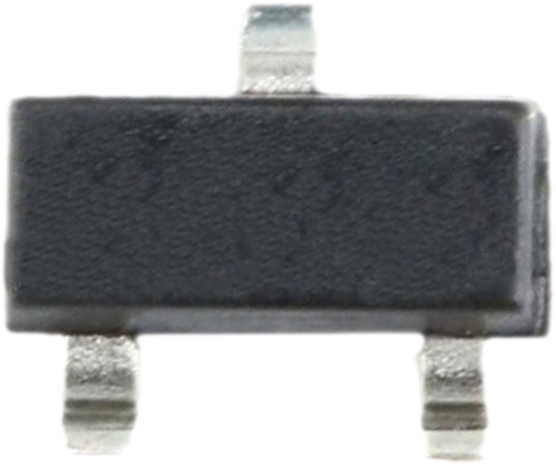
 Design with SMD MOSFET DMN2046U in Cirkit Designer
Introduction
The DMN2046U is a surface-mount N-channel MOSFET designed for low-voltage applications. Manufactured by Generic, this component is optimized for compact electronic devices requiring efficient power management and signal switching. Its low on-resistance and fast switching capabilities make it ideal for applications such as DC-DC converters, load switching, and battery-powered devices.
Explore Projects Built with SMD MOSFET DMN2046U
 Open Project in Cirkit Designer
 Open Project in Cirkit Designer
 Open Project in Cirkit Designer
 Open Project in Cirkit Designer
Explore Projects Built with SMD MOSFET DMN2046U
Open Project in Cirkit DesignerOpen Project in Cirkit DesignerOpen Project in Cirkit DesignerOpen Project in Cirkit DesignerCommon Applications
- Power management in portable electronics
- Signal switching in low-voltage circuits
- DC-DC converters
- Battery protection circuits
- Motor drivers for small motors
Technical Specifications
Key Specifications
| Parameter | Value |
|---|---|
| Manufacturer Part ID | DMN2046U |
| Type | N-Channel MOSFET |
| Maximum Drain-Source Voltage (VDS) | 20V |
| Maximum Gate-Source Voltage (VGS) | ±8V |
| Continuous Drain Current (ID) | 4.3A (at VGS = 4.5V) |
| Pulsed Drain Current (IDM) | 10A |
| On-Resistance (RDS(on)) | 0.045Ω (at VGS = 4.5V) |
| Power Dissipation (PD) | 1.25W |
| Operating Temperature | -55°C to +150°C |
| Package Type | SOT-23 |
Pin Configuration
The DMN2046U is housed in a compact SOT-23 package with three pins. The pinout is as follows:
| Pin Number | Pin Name | Description |
|---|---|---|
| 1 | Gate | Controls the MOSFET switching |
| 2 | Source | Connected to the source of the current |
| 3 | Drain | Connected to the load or output |
Usage Instructions
How to Use the DMN2046U in a Circuit
- Power Supply: Ensure the supply voltage does not exceed the maximum drain-source voltage (20V) or the gate-source voltage (±8V).
- Gate Drive: Use a gate voltage of 4.5V or higher to fully turn on the MOSFET and achieve low on-resistance.
- Load Connection: Connect the load between the drain pin and the positive supply voltage. The source pin should be connected to ground.
- Gate Resistor: Use a resistor (typically 10Ω to 100Ω) in series with the gate to limit inrush current and prevent damage to the MOSFET.
- Protection: Add a flyback diode across inductive loads (e.g., motors) to protect the MOSFET from voltage spikes during switching.
Example Circuit with Arduino UNO
The DMN2046U can be used to control a small DC motor with an Arduino UNO. Below is an example circuit and code:
Circuit Connections
- Drain (Pin 3): Connect to one terminal of the motor.
- Source (Pin 2): Connect to ground.
- Gate (Pin 1): Connect to an Arduino digital pin (e.g., D9) through a 100Ω resistor.
- The other terminal of the motor should be connected to the positive supply voltage (e.g., 5V).
- Add a flyback diode (e.g., 1N4007) across the motor terminals to protect the MOSFET.
Arduino Code
// Example code to control a motor using DMN2046U MOSFET
// Connect the MOSFET gate to pin D9 on the Arduino

const int motorPin = 9; // Pin connected to the MOSFET gate

void setup() {
  pinMode(motorPin, OUTPUT); // Set the motor pin as an output
}

void loop() {
  digitalWrite(motorPin, HIGH); // Turn the motor ON
  delay(1000);                  // Keep the motor ON for 1 second
  digitalWrite(motorPin, LOW);  // Turn the motor OFF
  delay(1000);                  // Keep the motor OFF for 1 second
}
Best Practices
- Avoid exceeding the maximum voltage and current ratings to prevent damage.
- Use proper heat dissipation techniques, such as a heatsink or PCB thermal vias, if operating near the maximum power dissipation.
- Ensure the gate voltage is sufficient to fully turn on the MOSFET for efficient operation.
Troubleshooting and FAQs
Common Issues and Solutions
MOSFET Overheating
- Cause: Exceeding the maximum current or insufficient heat dissipation.
- Solution: Reduce the load current or improve heat dissipation with a heatsink or thermal vias.
MOSFET Not Switching Properly
- Cause: Insufficient gate voltage or incorrect wiring.
- Solution: Ensure the gate voltage is at least 4.5V and verify the circuit connections.
Voltage Spikes Damaging the MOSFET
- Cause: Inductive loads generating back EMF.
- Solution: Add a flyback diode across the load to suppress voltage spikes.
MOSFET Always On or Off
- Cause: Gate pin floating or damaged MOSFET.
- Solution: Use a pull-down resistor (10kΩ) on the gate pin to ensure it is properly biased when not driven.
FAQs
Q1: Can the DMN2046U handle 12V loads?
A1: Yes, the DMN2046U can handle 12V loads as long as the current does not exceed 4.3A and proper heat dissipation is ensured.
Q2: Is the DMN2046U suitable for PWM applications?
A2: Yes, the DMN2046U's fast switching capabilities make it suitable for PWM control in applications like motor speed control and LED dimming.
Q3: Can I use the DMN2046U with a 3.3V logic level?
A3: The DMN2046U may not fully turn on with a 3.3V gate drive. For optimal performance, use a gate voltage of 4.5V or higher.
Q4: What is the maximum switching frequency for the DMN2046U?
A4: The maximum switching frequency depends on the gate drive circuit and load conditions. However, the DMN2046U is capable of operating in the MHz range with proper design.