How to Use 4 Channel Mosfet: Examples, Pinouts, and Specs
Introduction
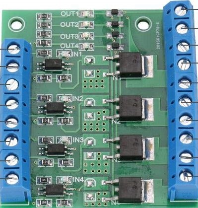
The 4 Channel MOSFET module by Hilitand, part ID X002W2O687, is a versatile electronic component that allows for the independent control and switching of four separate channels. This module is commonly used in applications that require the control of high-power devices such as motors, LEDs, and other electronic loads. It is particularly useful in projects where multiple outputs need to be controlled by a microcontroller, such as an Arduino UNO.
Explore Projects Built with 4 Channel Mosfet

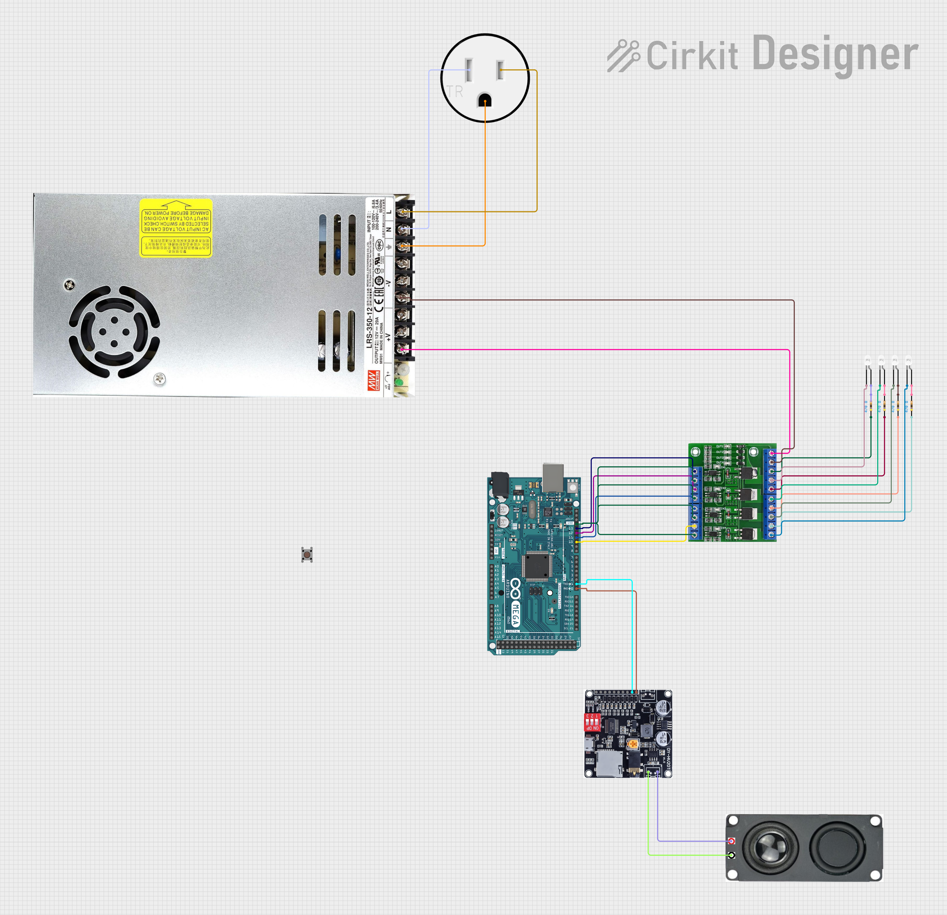

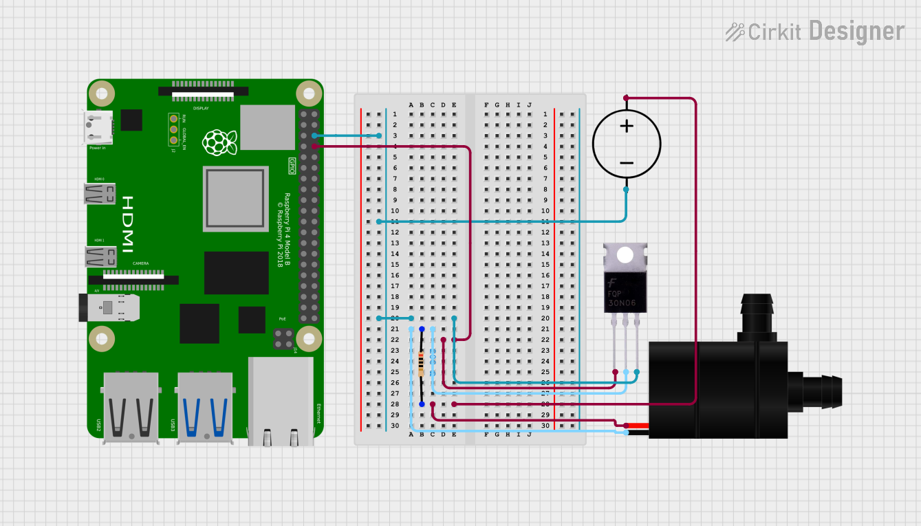
Explore Projects Built with 4 Channel Mosfet
Common Applications and Use Cases
- Driving multiple high-power LEDs
- Controlling the speed of DC motors
- Switching power to various electronic circuits
- Home automation systems for controlling appliances
- Robotics for controlling actuators and sensors
Technical Specifications
Key Technical Details
- Operating Voltage (Vcc): 3.3V to 5V
- Output Load Voltage (Vdss): 0V to 24V
- Output Load Current (Id): Up to 5A per channel
- Logic Level Voltage: 3.3V to 5V
- Total Power Dissipation (Pd): Dependent on heat sinking
Pin Configuration and Descriptions
| Pin Number | Pin Name | Description |
|---|---|---|
| 1 | Vcc | Power supply for the module (3.3V to 5V) |
| 2 | GND | Ground connection |
| 3 | IN1 | Input signal for Channel 1 |
| 4 | IN2 | Input signal for Channel 2 |
| 5 | IN3 | Input signal for Channel 3 |
| 6 | IN4 | Input signal for Channel 4 |
| 7 | OUT1 | Output to load for Channel 1 |
| 8 | OUT2 | Output to load for Channel 2 |
| 9 | OUT3 | Output to load for Channel 3 |
| 10 | OUT4 | Output to load for Channel 4 |
Usage Instructions
How to Use the Component in a Circuit
- Powering the Module: Connect the Vcc pin to a 3.3V or 5V power supply, and the GND pin to the ground of your power source.
- Connecting the Inputs: The IN1 to IN4 pins are connected to the digital outputs of a microcontroller, such as an Arduino UNO.
- Connecting the Loads: Connect the load you wish to control to the OUT1 to OUT4 pins, ensuring the load does not exceed the specified voltage and current ratings.
Important Considerations and Best Practices
- Heat Dissipation: Ensure adequate heat sinking for the MOSFETs when operating near the maximum power dissipation.
- Input Signal: The input signal voltage should match the logic level voltage of your microcontroller to ensure proper operation.
- Protective Measures: Consider using flyback diodes when controlling inductive loads to prevent voltage spikes.
Example Code for Arduino UNO
// Define the MOSFET control pins
const int mosfetPins[4] = {3, 5, 6, 9}; // Connect these pins to IN1, IN2, IN3, and IN4

void setup() {
  // Initialize all the MOSFET pins as output
  for (int i = 0; i < 4; i++) {
    pinMode(mosfetPins[i], OUTPUT);
  }
}

void loop() {
  // Turn on each MOSFET channel in sequence
  for (int i = 0; i < 4; i++) {
    digitalWrite(mosfetPins[i], HIGH); // Turn on the MOSFET
    delay(1000); // Wait for 1 second
    digitalWrite(mosfetPins[i], LOW); // Turn off the MOSFET
    delay(1000); // Wait for 1 second
  }
}
Troubleshooting and FAQs
Common Issues Users Might Face
- MOSFET Not Switching: Ensure that the input signal is within the correct voltage range and that the power supply is connected properly.
- Overheating: If the MOSFET is overheating, check if the current through the device is within the safe operating limits and improve heat dissipation.
- Load Not Operating: Verify that the load is connected correctly and does not exceed the maximum voltage and current ratings.
Solutions and Tips for Troubleshooting
- Check Connections: Double-check all connections, including power supply, ground, input signals, and load connections.
- Use a Multimeter: Measure the voltage at the input pins and the output pins to ensure the correct operation of the module.
- Test Each Channel Separately: Isolate and test each channel individually to identify if a particular channel is not functioning.
FAQs
Q: Can I control the MOSFETs with a 3.3V logic level? A: Yes, the module can be controlled with a 3.3V logic level, making it compatible with boards like the Raspberry Pi.
Q: What is the maximum current each channel can handle? A: Each channel can handle up to 5A of current, but ensure proper heat dissipation to prevent damage.
Q: Can I use PWM to control the brightness of an LED or the speed of a motor? A: Yes, you can use PWM signals from your microcontroller to control the brightness of LEDs or the speed of motors connected to the MOSFET module.