How to Use Multi link v1.0: Examples, Pinouts, and Specs
Introduction
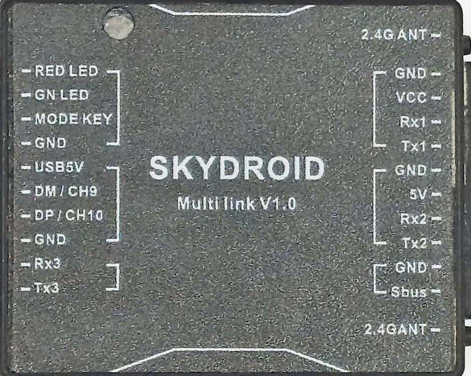
The Multi Link v1.0 by SKYDROID (Part ID: RF) is a versatile circuit component designed for connecting multiple signals or power sources in a compact and efficient manner. It is particularly useful in prototyping and modular designs, where flexibility and ease of connection are critical. This component simplifies the process of linking multiple inputs and outputs, making it an essential tool for engineers, hobbyists, and developers working on complex electronic systems.
Explore Projects Built with Multi link v1.0

Explore Projects Built with Multi link v1.0
Common Applications and Use Cases
- Prototyping and testing circuits with multiple signal or power connections.
- Modular electronic designs requiring quick and reliable interconnections.
- Signal distribution in robotics, IoT devices, and embedded systems.
- Power management in multi-source systems.
- Educational projects for demonstrating circuit connectivity.
Technical Specifications
Key Technical Details
| Parameter | Value |
|---|---|
| Manufacturer | SKYDROID |
| Part ID | RF |
| Operating Voltage Range | 3.3V to 12V |
| Maximum Current Rating | 2A per channel |
| Number of Channels | 4 |
| Dimensions | 25mm x 25mm x 10mm |
| Connector Type | Screw terminals |
| Material | PCB with copper traces |
| Operating Temperature | -20°C to 85°C |
Pin Configuration and Descriptions
The Multi Link v1.0 features four channels, each with two screw terminals for input and output connections. Below is the pin configuration:
| Pin Label | Description |
|---|---|
| IN1 | Input for Channel 1 |
| OUT1 | Output for Channel 1 |
| IN2 | Input for Channel 2 |
| OUT2 | Output for Channel 2 |
| IN3 | Input for Channel 3 |
| OUT3 | Output for Channel 3 |
| IN4 | Input for Channel 4 |
| OUT4 | Output for Channel 4 |
Usage Instructions
How to Use the Component in a Circuit
- Mounting the Component: Secure the Multi Link v1.0 on a breadboard or enclosure using screws or adhesive, ensuring it is stable.
- Connecting Inputs and Outputs:
- Use the screw terminals to connect input signals or power sources to the
INpins. - Connect the corresponding
OUTpins to the desired output devices or circuits.
- Use the screw terminals to connect input signals or power sources to the
- Powering the Circuit:
- Ensure the input voltage is within the operating range (3.3V to 12V).
- Avoid exceeding the maximum current rating of 2A per channel.
- Testing the Connections:
- Verify all connections are secure and free of short circuits.
- Power on the system and test the signal or power flow through the component.
Important Considerations and Best Practices
- Avoid Overloading: Do not exceed the maximum current rating of 2A per channel to prevent damage.
- Proper Insulation: Ensure all connections are insulated to avoid accidental short circuits.
- Heat Management: If operating at high currents, ensure adequate ventilation to prevent overheating.
- Polarity Check: Double-check the polarity of input and output connections to avoid reverse polarity damage.
Example: Using Multi Link v1.0 with Arduino UNO
The Multi Link v1.0 can be used to distribute signals from an Arduino UNO to multiple devices. Below is an example of connecting an LED to each channel:
Circuit Setup
- Connect the Arduino's digital pins (e.g., D2, D3, D4, D5) to the
INpins of the Multi Link v1.0. - Connect LEDs with appropriate resistors to the
OUTpins. - Power the Multi Link v1.0 using the Arduino's 5V and GND pins.
Arduino Code
// Define the pins connected to the Multi Link v1.0
const int channel1 = 2; // Channel 1 input connected to Arduino pin 2
const int channel2 = 3; // Channel 2 input connected to Arduino pin 3
const int channel3 = 4; // Channel 3 input connected to Arduino pin 4
const int channel4 = 5; // Channel 4 input connected to Arduino pin 5

void setup() {
  // Set the channel pins as outputs
  pinMode(channel1, OUTPUT);
  pinMode(channel2, OUTPUT);
  pinMode(channel3, OUTPUT);
  pinMode(channel4, OUTPUT);
}

void loop() {
  // Turn on LEDs connected to all channels
  digitalWrite(channel1, HIGH); // Turn on LED on Channel 1
  digitalWrite(channel2, HIGH); // Turn on LED on Channel 2
  digitalWrite(channel3, HIGH); // Turn on LED on Channel 3
  digitalWrite(channel4, HIGH); // Turn on LED on Channel 4
  delay(1000); // Wait for 1 second

  // Turn off LEDs connected to all channels
  digitalWrite(channel1, LOW);  // Turn off LED on Channel 1
  digitalWrite(channel2, LOW);  // Turn off LED on Channel 2
  digitalWrite(channel3, LOW);  // Turn off LED on Channel 3
  digitalWrite(channel4, LOW);  // Turn off LED on Channel 4
  delay(1000); // Wait for 1 second
}
Troubleshooting and FAQs
Common Issues Users Might Face
No Signal or Power Output:
- Cause: Loose or incorrect connections.
- Solution: Double-check all connections and ensure the screw terminals are tightened securely.
Overheating:
- Cause: Exceeding the maximum current rating of 2A per channel.
- Solution: Reduce the load on the affected channel or distribute the load across multiple channels.
Short Circuit:
- Cause: Improper insulation or accidental contact between terminals.
- Solution: Inspect the connections and ensure proper insulation.
Signal Interference:
- Cause: High-frequency signals causing crosstalk between channels.
- Solution: Use shielded cables or separate high-frequency signals from low-frequency ones.
FAQs
Q1: Can the Multi Link v1.0 handle AC signals?
A1: Yes, it can handle low-voltage AC signals within the specified voltage and current ratings.
Q2: Is the component waterproof?
A2: No, the Multi Link v1.0 is not waterproof. Use it in dry environments or enclosures.
Q3: Can I use it for high-power applications?
A3: The component is designed for low-power applications. For high-power systems, consider using relays or other suitable components.
Q4: How do I clean the component?
A4: Use a soft, dry cloth to clean the PCB. Avoid using liquids or abrasive materials.
This concludes the documentation for the Multi Link v1.0. For further assistance, refer to the manufacturer's support resources or contact SKYDROID directly.