How to Use TL072: Examples, Pinouts, and Specs
Introduction
The TL072 is a low-noise JFET-input operational amplifier (op-amp) designed for high-speed and low-distortion applications. It features a dual op-amp configuration, making it ideal for use in audio processing, signal amplification, and active filter designs. The TL072 is widely appreciated for its low input bias current, high slew rate, and excellent noise performance, making it a popular choice in both professional and hobbyist electronics projects.
Explore Projects Built with TL072


Explore Projects Built with TL072
Common Applications and Use Cases
- Audio preamplifiers and mixers
- Active filters and equalizers
- Signal conditioning circuits
- Oscillators and waveform generators
- Analog computing and instrumentation
Technical Specifications
The TL072 is a versatile op-amp with the following key technical specifications:
| Parameter | Value |
|---|---|
| Supply Voltage (Vcc) | ±3V to ±18V (dual supply) |
| Input Offset Voltage | 3mV (typical) |
| Input Bias Current | 65pA (typical) |
| Slew Rate | 13V/µs (typical) |
| Gain Bandwidth Product | 3MHz (typical) |
| Input Impedance | 10⁹Ω (high impedance) |
| Output Voltage Swing | ±12V (with ±15V supply) |
| Noise Voltage Density | 18nV/√Hz (at 1kHz) |
| Operating Temperature Range | 0°C to 70°C |
| Package Types | DIP-8, SOIC-8, TSSOP-8 |
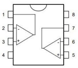
Pin Configuration and Descriptions
The TL072 is typically available in an 8-pin package. Below is the pinout and description:
| Pin Number | Pin Name | Description |
|---|---|---|
| 1 | Output A | Output of the first operational amplifier |
| 2 | Inverting Input A | Inverting input of the first op-amp |
| 3 | Non-Inverting Input A | Non-inverting input of the first op-amp |
| 4 | V- (GND) | Negative power supply or ground |
| 5 | Non-Inverting Input B | Non-inverting input of the second op-amp |
| 6 | Inverting Input B | Inverting input of the second op-amp |
| 7 | Output B | Output of the second operational amplifier |
| 8 | V+ | Positive power supply |
Usage Instructions
How to Use the TL072 in a Circuit
- Power Supply: Connect the TL072 to a dual power supply (e.g., ±12V or ±15V) for optimal performance. The V+ pin (pin 8) connects to the positive voltage, and the V- pin (pin 4) connects to the negative voltage or ground.
- Input Connections: Use the inverting (pins 2 and 6) and non-inverting (pins 3 and 5) inputs to configure the op-amp for your desired application (e.g., as an amplifier, buffer, or filter).
- Output: The outputs (pins 1 and 7) provide the amplified or processed signal. Ensure the load impedance is appropriate to avoid distortion.
- Bypass Capacitors: Place decoupling capacitors (e.g., 0.1µF ceramic and 10µF electrolytic) close to the power supply pins to reduce noise and improve stability.
Important Considerations and Best Practices
- Input Impedance: The TL072 has a high input impedance, making it suitable for high-impedance signal sources.
- Avoid Overloading: Ensure the output load does not exceed the op-amp's drive capability to prevent distortion or instability.
- Temperature Range: Operate the TL072 within its specified temperature range (0°C to 70°C) for reliable performance.
- PCB Layout: Use a clean and low-noise PCB layout, especially in audio applications, to minimize interference.
Example: Using TL072 with Arduino UNO
The TL072 can be used to amplify an analog signal before feeding it into the Arduino's ADC (Analog-to-Digital Converter). Below is an example of a simple non-inverting amplifier circuit and Arduino code to read the amplified signal.
Circuit Diagram
- Connect the signal source to the non-inverting input (pin 3) of the TL072.
- Use a resistor divider network to set the gain of the amplifier.
- Connect the output (pin 1) of the TL072 to the Arduino's analog input (e.g., A0).
Arduino Code
// Arduino code to read an amplified signal from the TL072
const int analogPin = A0; // Pin A0 is connected to the TL072 output
int signalValue = 0;      // Variable to store the analog signal value

void setup() {
  Serial.begin(9600); // Initialize serial communication at 9600 baud
}

void loop() {
  signalValue = analogRead(analogPin); // Read the analog signal
  Serial.print("Signal Value: ");
  Serial.println(signalValue); // Print the signal value to the Serial Monitor
  delay(100); // Delay for 100ms before the next reading
}
Troubleshooting and FAQs
Common Issues and Solutions
No Output Signal:
- Cause: Incorrect power supply connections.
- Solution: Verify that V+ and V- are connected to the correct voltage levels.
Distorted Output:
- Cause: Overloading the output or insufficient power supply decoupling.
- Solution: Reduce the load impedance or add bypass capacitors near the power pins.
High Noise Levels:
- Cause: Poor PCB layout or external interference.
- Solution: Use proper grounding techniques and shield sensitive signal paths.
Amplifier Not Working as Expected:
- Cause: Incorrect resistor values in the feedback network.
- Solution: Double-check the resistor values and ensure they match the desired gain configuration.
FAQs
Q1: Can the TL072 operate with a single power supply?
A1: Yes, the TL072 can operate with a single supply (e.g., 0V and +12V), but the input and output signals must be biased appropriately to stay within the op-amp's operating range.
Q2: What is the maximum gain I can achieve with the TL072?
A2: The maximum gain depends on the feedback network and the bandwidth of the op-amp. For high gains, ensure the signal frequency is within the op-amp's gain-bandwidth product.
Q3: Is the TL072 suitable for battery-powered applications?
A3: Yes, the TL072's low power consumption makes it suitable for battery-powered circuits, provided the supply voltage is within the specified range.
Q4: Can I use the TL072 for high-frequency applications?
A4: The TL072 is suitable for low to moderate frequency applications (up to a few hundred kHz). For higher frequencies, consider op-amps with a higher gain-bandwidth product.