
How to Use 3-Axis Accelerometer Breakout - MMA8452Q: Examples, Pinouts, and Specs
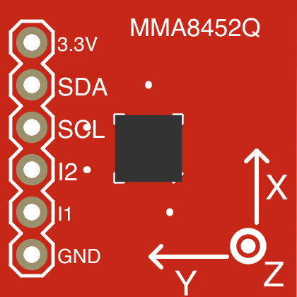
 Design with 3-Axis Accelerometer Breakout - MMA8452Q in Cirkit Designer
Introduction
The 3-Axis Accelerometer Breakout - MMA8452Q by SparkFun is a compact and versatile sensor module designed to measure acceleration along three axes: X, Y, and Z. It features the MMA8452Q accelerometer, a low-power, high-performance device capable of detecting motion, orientation, and free-fall events. The module communicates via an I2C interface, making it easy to integrate into microcontroller-based projects.
Explore Projects Built with 3-Axis Accelerometer Breakout - MMA8452Q
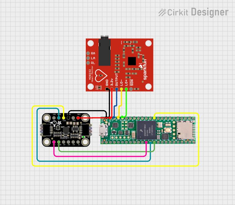 Open Project in Cirkit Designer
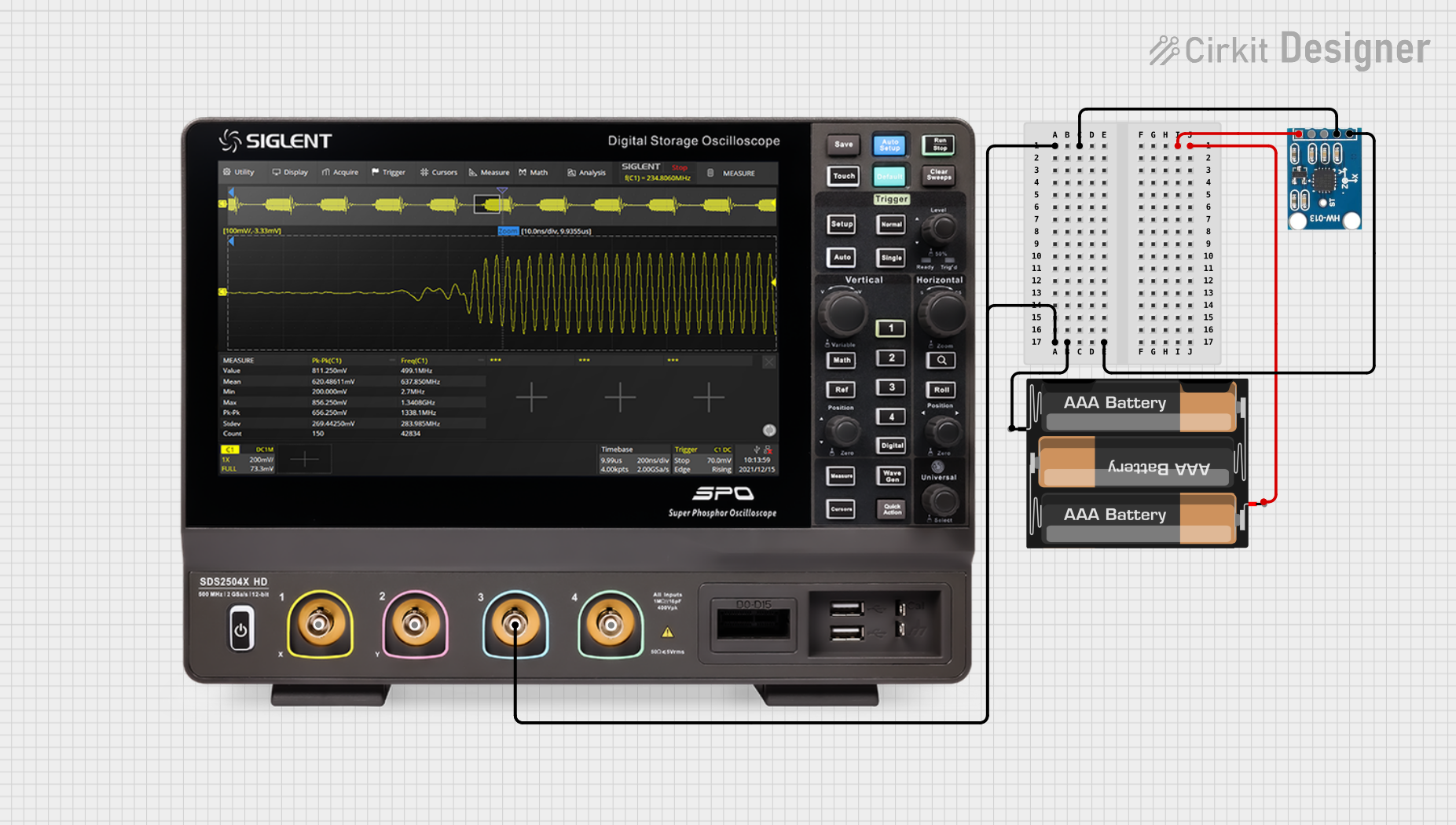 Open Project in Cirkit Designer
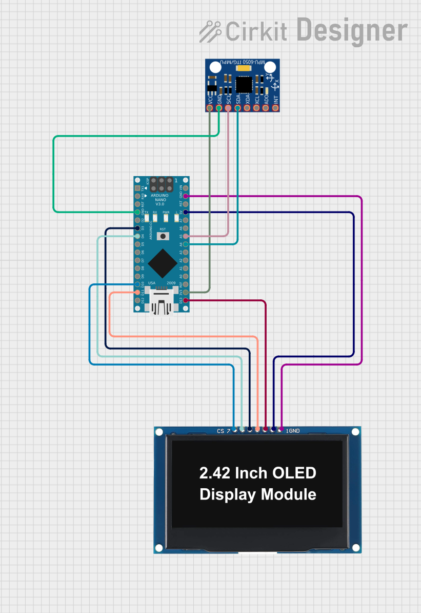 Open Project in Cirkit Designer
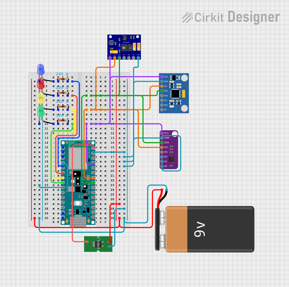 Open Project in Cirkit Designer
Explore Projects Built with 3-Axis Accelerometer Breakout - MMA8452Q
Open Project in Cirkit DesignerOpen Project in Cirkit DesignerOpen Project in Cirkit DesignerOpen Project in Cirkit DesignerCommon Applications
- Motion detection and gesture recognition
- Orientation sensing for mobile devices
- Free-fall detection for safety systems
- Robotics and drone stabilization
- Wearable devices and fitness trackers
Technical Specifications
Below are the key technical details of the MMA8452Q breakout board:
| Parameter | Value |
|---|---|
| Operating Voltage | 1.95V to 3.6V |
| Logic Level | 3.3V (I2C pull-ups are 3.3V) |
| Communication Interface | I2C (7-bit address: 0x1C or 0x1D) |
| Measurement Range | ±2g, ±4g, ±8g (configurable) |
| Output Data Rate (ODR) | 1.56 Hz to 800 Hz |
| Sensitivity | 1024 LSB/g (±2g), 512 LSB/g (±4g), 256 LSB/g (±8g) |
| Power Consumption | 6 µA in standby, 165 µA in active mode |
| Dimensions | 0.8" x 0.8" (20.3mm x 20.3mm) |
Pin Configuration
The breakout board has six pins, as described in the table below:
| Pin | Name | Description |
|---|---|---|
| 1 | GND | Ground connection |
| 2 | 3.3V | Power supply input (3.3V) |
| 3 | SDA | I2C data line |
| 4 | SCL | I2C clock line |
| 5 | INT1 | Interrupt 1 output (configurable for motion detection, orientation, etc.) |
| 6 | INT2 | Interrupt 2 output (configurable for additional interrupt sources) |
Usage Instructions
Connecting the MMA8452Q to an Arduino UNO
To use the MMA8452Q breakout board with an Arduino UNO, follow these steps:
- Connect the GND pin of the breakout board to the GND pin on the Arduino.
- Connect the 3.3V pin of the breakout board to the 3.3V pin on the Arduino.
- Connect the SDA pin of the breakout board to the A4 pin on the Arduino (I2C data line).
- Connect the SCL pin of the breakout board to the A5 pin on the Arduino (I2C clock line).
- Optionally, connect the INT1 and/or INT2 pins to any digital pins on the Arduino for interrupt-based functionality.
Example Arduino Code
Below is an example Arduino sketch to read acceleration data from the MMA8452Q:
#include <Wire.h>

// MMA8452Q I2C address
#define MMA8452Q_ADDR 0x1C

// Register addresses
#define REG_CTRL_REG1 0x2A
#define REG_OUT_X_MSB 0x01

void setup() {
  Wire.begin(); // Initialize I2C communication
  Serial.begin(9600); // Initialize serial communication for debugging

  // Configure MMA8452Q
  Wire.beginTransmission(MMA8452Q_ADDR);
  Wire.write(REG_CTRL_REG1); // Access control register 1
  Wire.write(0x01); // Set active mode
  Wire.endTransmission();

  Serial.println("MMA8452Q initialized.");
}

void loop() {
  int16_t x, y, z;

  // Request 6 bytes of acceleration data (X, Y, Z)
  Wire.beginTransmission(MMA8452Q_ADDR);
  Wire.write(REG_OUT_X_MSB); // Start reading from OUT_X_MSB register
  Wire.endTransmission(false);
  Wire.requestFrom(MMA8452Q_ADDR, 6);

  if (Wire.available() == 6) {
    x = (Wire.read() << 8) | Wire.read(); // Combine MSB and LSB for X-axis
    y = (Wire.read() << 8) | Wire.read(); // Combine MSB and LSB for Y-axis
    z = (Wire.read() << 8) | Wire.read(); // Combine MSB and LSB for Z-axis

    // Convert raw data to g values (assuming ±2g range)
    float x_g = x / 1024.0;
    float y_g = y / 1024.0;
    float z_g = z / 1024.0;

    // Print acceleration values
    Serial.print("X: "); Serial.print(x_g); Serial.print(" g, ");
    Serial.print("Y: "); Serial.print(y_g); Serial.print(" g, ");
    Serial.print("Z: "); Serial.print(z_g); Serial.println(" g");
  }

  delay(100); // Delay for readability
}
Important Considerations
- Ensure the breakout board is powered with 3.3V. Supplying 5V may damage the module.
- Use appropriate pull-up resistors for the I2C lines if they are not already present on the breakout board.
- Configure the measurement range (±2g, ±4g, or ±8g) based on your application requirements by modifying the control registers.
Troubleshooting and FAQs
Common Issues
No data or incorrect readings from the sensor.
- Ensure the I2C connections (SDA and SCL) are properly wired.
- Verify the I2C address (default is 0x1C, but it may be 0x1D if the SA0 pin is pulled high).
- Check the power supply voltage (must be 3.3V).
Arduino hangs or crashes during I2C communication.
- Ensure pull-up resistors are present on the SDA and SCL lines.
- Verify that no other devices on the I2C bus are causing address conflicts.
Interrupts are not triggering as expected.
- Confirm that the interrupt pins (INT1/INT2) are connected to the correct Arduino pins.
- Configure the interrupt registers in the MMA8452Q to enable the desired interrupt sources.
Tips for Troubleshooting
- Use an I2C scanner sketch to confirm the sensor's address on the I2C bus.
- Check the MMA8452Q datasheet for detailed register descriptions and configuration options.
- If using a 5V microcontroller, use a logic level shifter to safely interface with the 3.3V I2C lines.
By following this documentation, you should be able to successfully integrate and use the 3-Axis Accelerometer Breakout - MMA8452Q in your projects.