
How to Use MCP23017: Examples, Pinouts, and Specs
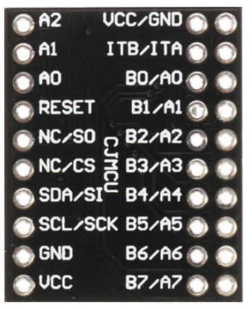
 Design with MCP23017 in Cirkit Designer
Introduction
The MCP23017, manufactured by AzDelivery, is a 16-bit I/O expander that communicates with microcontrollers via the I2C interface. It allows users to add additional input/output pins to their projects, making it an ideal solution for applications requiring more GPIOs than what is available on the microcontroller. The MCP23017 is highly versatile and can be used for both input and output operations, supporting features such as interrupt handling and configurable pull-up resistors.
Explore Projects Built with MCP23017
 Open Project in Cirkit Designer
 Open Project in Cirkit Designer
 Open Project in Cirkit Designer
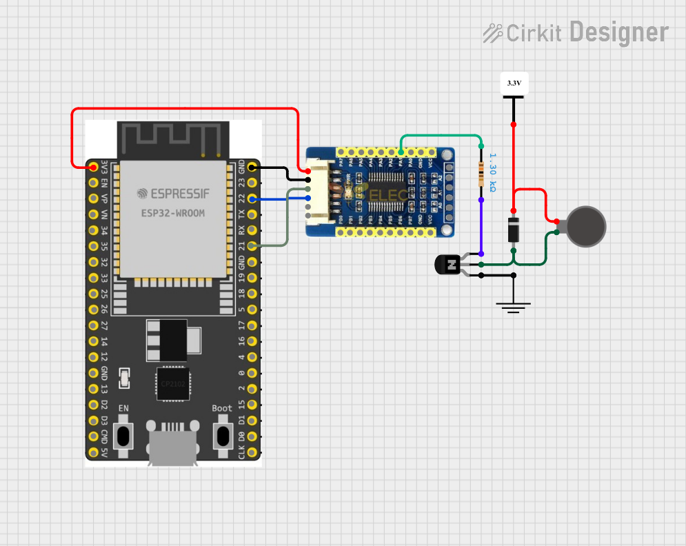 Open Project in Cirkit Designer
Explore Projects Built with MCP23017
Open Project in Cirkit DesignerOpen Project in Cirkit DesignerOpen Project in Cirkit DesignerOpen Project in Cirkit DesignerCommon Applications and Use Cases
- Expanding GPIO pins for microcontrollers like Arduino, Raspberry Pi, and ESP32
- Driving LEDs, relays, or other output devices
- Reading multiple switches, sensors, or other input devices
- Home automation systems
- Robotics and industrial control systems
Technical Specifications
The MCP23017 is designed to operate efficiently in a wide range of applications. Below are its key technical specifications:
| Parameter | Value |
|---|---|
| Operating Voltage | 1.8V to 5.5V |
| Communication Interface | I2C (up to 1.7 MHz) |
| Number of I/O Pins | 16 (organized as two 8-bit ports) |
| Maximum Sink Current | 25 mA per pin |
| Maximum Source Current | 25 mA per pin |
| Interrupt Capability | Yes (configurable for each pin) |
| Internal Pull-Up Resistors | Yes (100 kΩ typical) |
| Package Type | DIP, SOIC, SSOP |
Pin Configuration and Descriptions
The MCP23017 has 28 pins, with the following configuration:
| Pin Number | Pin Name | Description |
|---|---|---|
| 1-3 | A2, A1, A0 | Address pins for I2C communication. Used to set the I2C address of the device. |
| 4 | RESET | Active-low reset input. Resets the device when pulled low. |
| 5 | INTB | Interrupt output for Port B. |
| 6 | INTA | Interrupt output for Port A. |
| 7-14 | GPA0-GPA7 | General-purpose I/O pins for Port A. |
| 15 | VSS | Ground (0V). |
| 16-23 | GPB0-GPB7 | General-purpose I/O pins for Port B. |
| 24 | VDD | Power supply (1.8V to 5.5V). |
| 25 | SCL | I2C clock line. |
| 26 | SDA | I2C data line. |
| 27 | NC | No connection. |
| 28 | NC | No connection. |
Usage Instructions
The MCP23017 is straightforward to use in a circuit. Below are the steps and considerations for integrating it into your project:
Connecting the MCP23017
- Power Supply: Connect the VDD pin to a 3.3V or 5V power source and the VSS pin to ground.
- I2C Addressing: Use the A2, A1, and A0 pins to set the I2C address. These pins can be connected to VDD (logic high) or VSS (logic low) to configure the address. The MCP23017 supports up to 8 unique addresses.
- I2C Lines: Connect the SCL and SDA pins to the corresponding I2C lines on your microcontroller. Use pull-up resistors (typically 4.7 kΩ) on these lines if not already present.
- GPIO Pins: Use the GPA0-GPA7 and GPB0-GPB7 pins as input or output, depending on your application. Configure these pins via the I2C interface.
- Interrupts (Optional): If using interrupts, connect the INTA and/or INTB pins to interrupt-capable pins on your microcontroller.
Example: Using MCP23017 with Arduino UNO
Below is an example of how to use the MCP23017 with an Arduino UNO to control LEDs and read switches.
Circuit Diagram
- Connect VDD to the 5V pin on the Arduino and VSS to GND.
- Connect SCL to A5 and SDA to A4 on the Arduino UNO.
- Use pull-up resistors (4.7 kΩ) on the SCL and SDA lines.
- Connect LEDs to GPA0-GPA3 with current-limiting resistors.
- Connect switches to GPB0-GPB3 with pull-up resistors enabled in the MCP23017.
Arduino Code
#include <Wire.h>
#include "Adafruit_MCP23017.h"

// Create an MCP23017 object
Adafruit_MCP23017 mcp;

void setup() {
  Wire.begin(); // Initialize I2C communication
  mcp.begin();  // Initialize MCP23017 with default address (0x20)

  // Configure GPA0-GPA3 as outputs for LEDs
  for (int i = 0; i < 4; i++) {
    mcp.pinMode(i, OUTPUT);
  }

  // Configure GPB0-GPB3 as inputs for switches
  for (int i = 8; i < 12; i++) {
    mcp.pinMode(i, INPUT);
    mcp.pullUp(i, HIGH); // Enable internal pull-up resistors
  }
}

void loop() {
  // Turn on LEDs connected to GPA0-GPA3
  for (int i = 0; i < 4; i++) {
    mcp.digitalWrite(i, HIGH);
    delay(500); // Wait for 500ms
    mcp.digitalWrite(i, LOW);
  }

  // Read switches connected to GPB0-GPB3
  for (int i = 8; i < 12; i++) {
    if (mcp.digitalRead(i) == LOW) {
      // Switch is pressed
      Serial.print("Switch ");
      Serial.print(i - 8);
      Serial.println(" is pressed");
    }
  }
}
Important Considerations and Best Practices
- Ensure the I2C pull-up resistors are present on the SCL and SDA lines.
- Avoid exceeding the maximum current ratings for the GPIO pins (25 mA per pin).
- Use decoupling capacitors (e.g., 0.1 µF) near the VDD pin to stabilize the power supply.
- Configure unused GPIO pins as inputs with pull-ups enabled to prevent floating states.
Troubleshooting and FAQs
Common Issues
I2C Communication Failure:
- Cause: Incorrect I2C address or missing pull-up resistors.
- Solution: Verify the address configuration using the A2, A1, and A0 pins. Ensure pull-up resistors are connected to the SCL and SDA lines.
GPIO Pins Not Responding:
- Cause: Incorrect pin configuration or wiring.
- Solution: Double-check the pinMode and digitalWrite/digitalRead settings in your code. Verify the wiring.
Interrupts Not Triggering:
- Cause: Interrupts not properly configured.
- Solution: Ensure the interrupt pins (INTA/INTB) are connected to interrupt-capable pins on the microcontroller. Configure the interrupt control registers correctly.
FAQs
Can the MCP23017 operate at 3.3V?
- Yes, the MCP23017 supports operating voltages from 1.8V to 5.5V.
How many MCP23017 devices can I connect to a single I2C bus?
- Up to 8 devices can be connected by configuring the A2, A1, and A0 address pins.
What is the maximum I2C clock speed supported?
- The MCP23017 supports I2C clock speeds up to 1.7 MHz.
Can I use the MCP23017 with a Raspberry Pi?
- Yes, the MCP23017 is fully compatible with the Raspberry Pi's I2C interface.