How to Use Potentiometer Piher 10mm: Examples, Pinouts, and Specs
Introduction
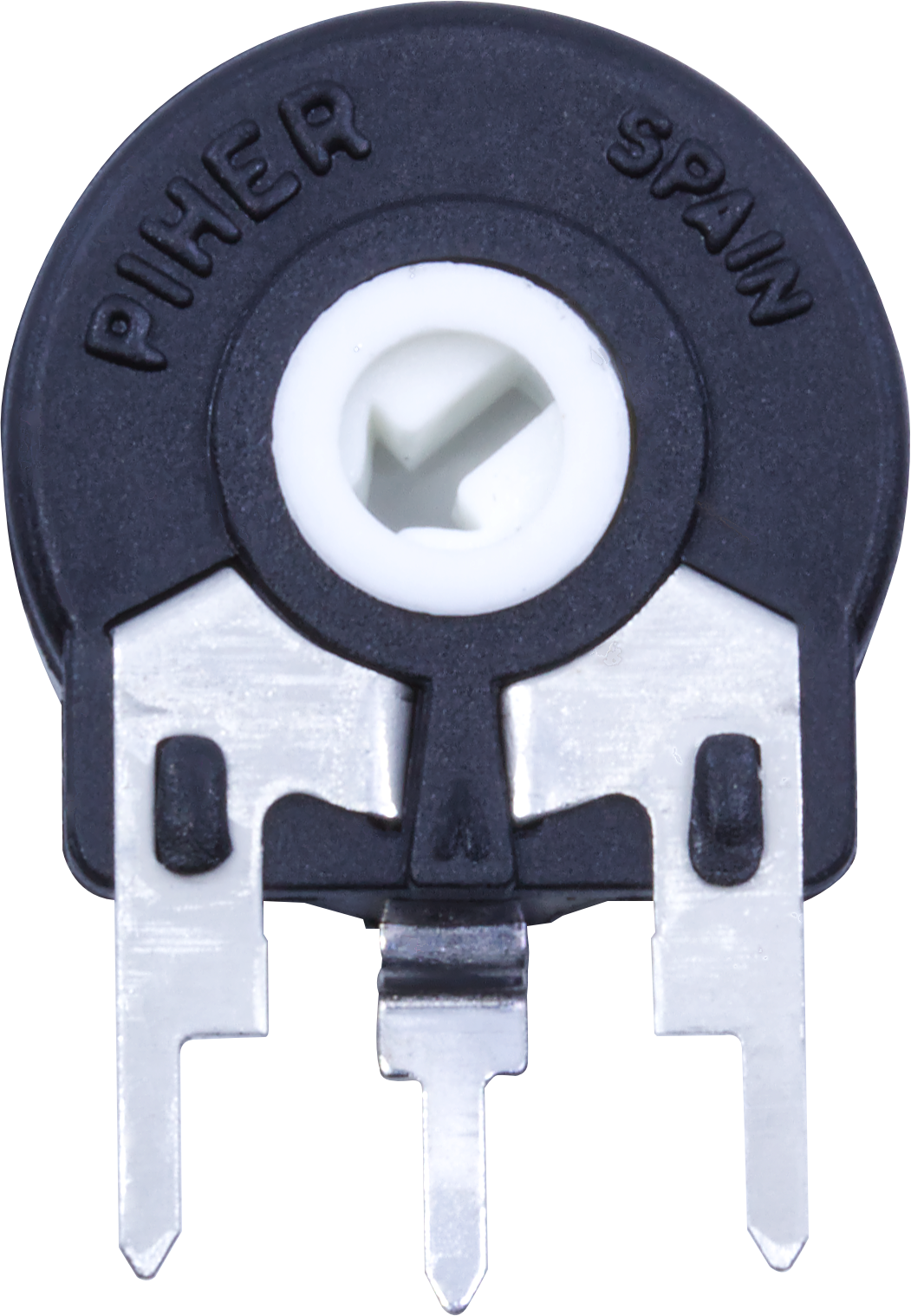
The Potentiometer Piher 10mm is a compact, rotary variable resistor designed for precise control of electrical signals in electronic circuits. Manufactured by Piher, this 10mm potentiometer is widely used for adjusting voltage levels, tuning circuits, and controlling parameters such as volume, brightness, or speed in various applications. Its small size and reliable performance make it a popular choice for both hobbyist and professional projects.
Explore Projects Built with Potentiometer Piher 10mm
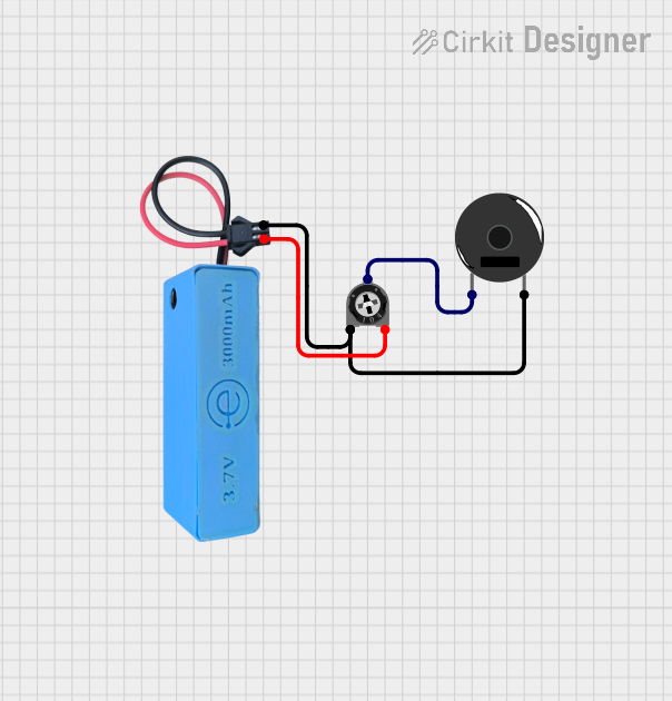

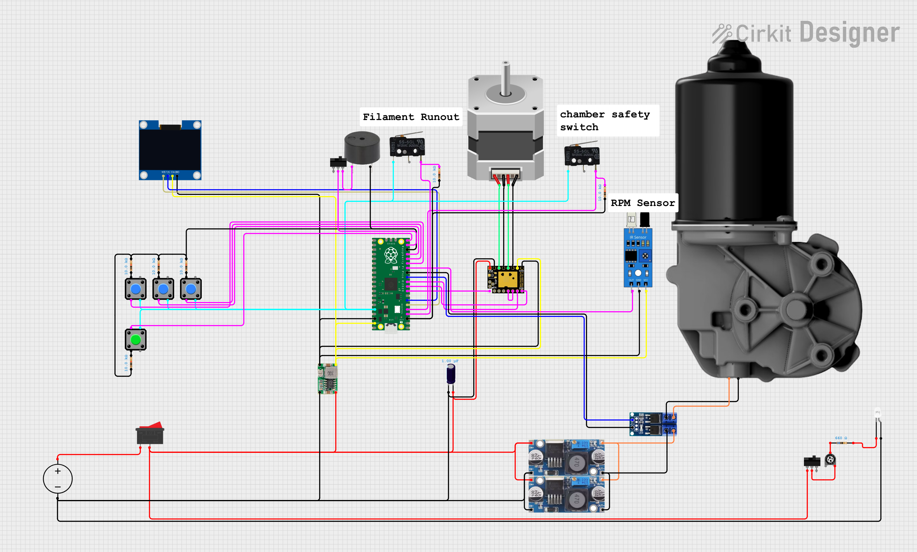
Explore Projects Built with Potentiometer Piher 10mm
Common Applications and Use Cases
- Audio Equipment: Volume and tone control in amplifiers and speakers.
- Lighting Systems: Brightness adjustment in LED circuits.
- Motor Control: Speed regulation in DC motor drivers.
- Sensor Calibration: Fine-tuning sensor outputs in measurement systems.
- Prototyping: Adjustable resistance for testing and development.
Technical Specifications
The following table outlines the key technical details of the Potentiometer Piher 10mm:
| Parameter | Specification |
|---|---|
| Resistance Range | 1 kΩ to 1 MΩ (varies by model) |
| Tolerance | ±20% |
| Power Rating | 0.15 W (at 70°C) |
| Maximum Voltage | 250 V DC |
| Rotational Life | 10,000 cycles |
| Operating Temperature | -10°C to +70°C |
| Shaft Type | Rotary |
| Shaft Length | 5 mm to 20 mm (varies by model) |
| Mounting Type | Through-hole |
| Adjustment Type | Top or side adjustment (varies) |
Pin Configuration and Descriptions
The Potentiometer Piher 10mm typically has three pins, as described below:
| Pin Number | Name | Description |
|---|---|---|
| 1 | Terminal 1 | One end of the resistive track. Connect to ground or a fixed voltage source. |
| 2 | Wiper | The adjustable middle pin. Outputs the variable resistance or voltage. |
| 3 | Terminal 2 | The other end of the resistive track. Connect to a fixed voltage source or load. |
Usage Instructions
How to Use the Potentiometer in a Circuit
- Identify the Pins: Locate the three pins (Terminal 1, Wiper, Terminal 2) on the potentiometer.
- Connect the Circuit:
- Connect Terminal 1 to ground or a fixed voltage source.
- Connect Terminal 2 to a fixed voltage source or load.
- Connect the Wiper (middle pin) to the input of the circuit where variable resistance or voltage is required.
- Adjust the Resistance: Rotate the shaft to change the resistance between the wiper and the terminals. This adjusts the output voltage or current in the circuit.
Important Considerations and Best Practices
- Power Rating: Ensure the power dissipation across the potentiometer does not exceed its rated 0.15 W.
- Mechanical Stress: Avoid applying excessive force to the shaft to prevent damage.
- Temperature Range: Operate the potentiometer within its specified temperature range (-10°C to +70°C).
- Debouncing: If used in digital circuits, consider adding a capacitor to smooth out noise caused by mechanical movement.
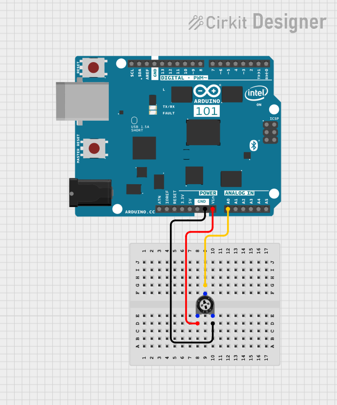
Example: Using the Potentiometer with an Arduino UNO
The Potentiometer Piher 10mm can be used with an Arduino UNO to read analog values and control outputs such as an LED's brightness. Below is an example code:
// Example: Reading potentiometer value and controlling LED brightness
const int potPin = A0;  // Connect the wiper (middle pin) to analog pin A0
const int ledPin = 9;   // Connect an LED to digital pin 9 (PWM pin)

void setup() {
  pinMode(ledPin, OUTPUT);  // Set the LED pin as an output
  Serial.begin(9600);       // Initialize serial communication for debugging
}

void loop() {
  int potValue = analogRead(potPin);  // Read the potentiometer value (0-1023)

  // Map the potentiometer value to a PWM range (0-255)
  int ledBrightness = map(potValue, 0, 1023, 0, 255);

  analogWrite(ledPin, ledBrightness);  // Set the LED brightness

  // Print the potentiometer value for debugging
  Serial.print("Potentiometer Value: ");
  Serial.println(potValue);

  delay(100);  // Small delay for stability
}
Troubleshooting and FAQs
Common Issues and Solutions
No Output Voltage from the Wiper:
- Cause: Incorrect wiring or loose connections.
- Solution: Verify the pin connections and ensure the potentiometer is properly soldered or inserted into the breadboard.
Inconsistent or Noisy Output:
- Cause: Dust or wear on the resistive track.
- Solution: Clean the potentiometer with contact cleaner or replace it if worn out.
Potentiometer Shaft Feels Stiff or Loose:
- Cause: Mechanical damage or wear.
- Solution: Replace the potentiometer if the shaft is damaged or excessively worn.
Overheating:
- Cause: Exceeding the power rating.
- Solution: Ensure the power dissipation is within the specified 0.15 W limit.
FAQs
Q: Can the potentiometer be used as a variable resistor?
A: Yes, by connecting only two pins (one terminal and the wiper), the potentiometer can function as a variable resistor.Q: Is the Potentiometer Piher 10mm waterproof?
A: No, this potentiometer is not waterproof. Avoid exposure to moisture or liquids.Q: Can I use this potentiometer for high-current applications?
A: No, the potentiometer is designed for low-power applications with a maximum power rating of 0.15 W.Q: How do I mount the potentiometer on a PCB?
A: The potentiometer has through-hole pins for easy soldering onto a printed circuit board (PCB).
This documentation provides a comprehensive guide to understanding, using, and troubleshooting the Potentiometer Piher 10mm.