How to Use Adafruit OLED Monochrome 0.91in I2C with STEMMA QT: Examples, Pinouts, and Specs
Introduction
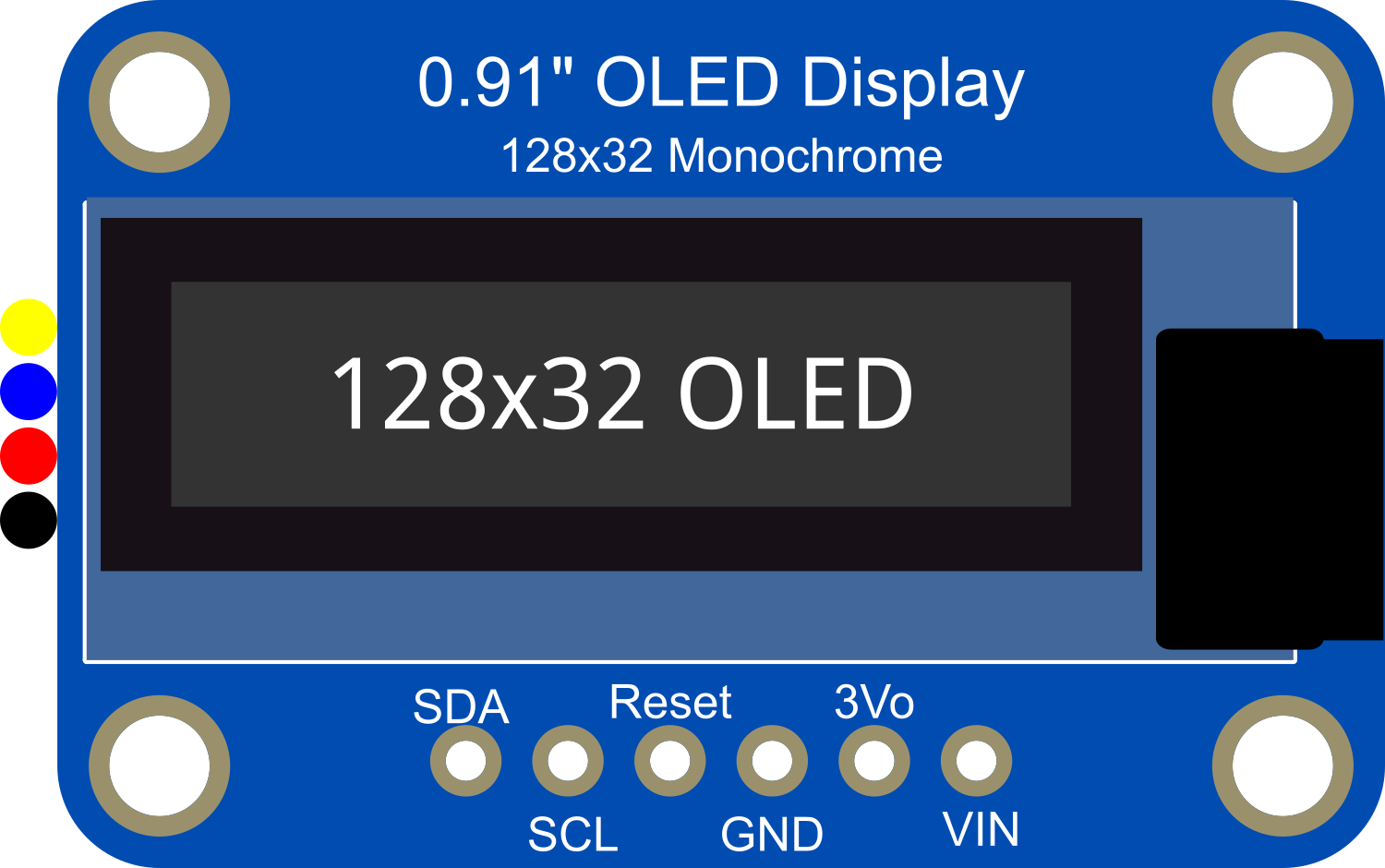
The Adafruit OLED Monochrome 0.91in I2C display is a compact and versatile display module suitable for adding a small, high-contrast visual interface to your electronics projects. With a resolution of 128x32 pixels, it provides sufficient space for simple graphics, text, and symbols. This display uses the I2C communication protocol, making it easy to interface with microcontrollers and development boards like the Arduino UNO. The inclusion of STEMMA QT connectors allows for quick and solderless connections, making it ideal for prototyping and educational purposes.
Explore Projects Built with Adafruit OLED Monochrome 0.91in I2C with STEMMA QT


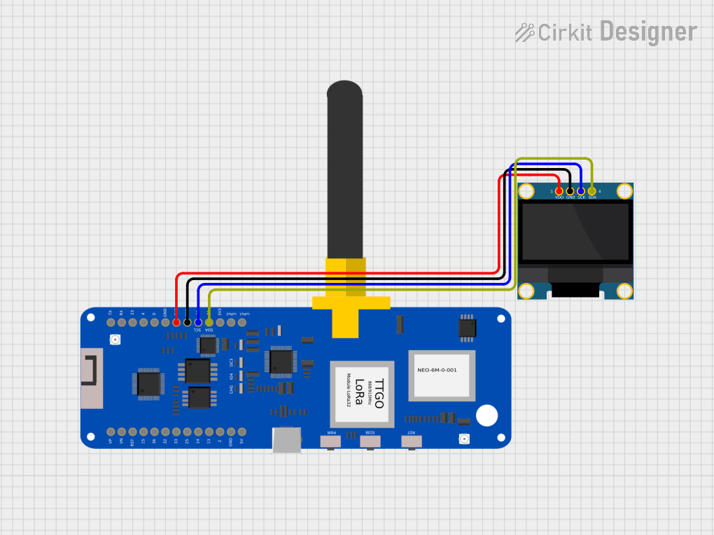
Explore Projects Built with Adafruit OLED Monochrome 0.91in I2C with STEMMA QT
Common Applications and Use Cases
- Wearable devices
- Portable instruments
- User interfaces for small-scale projects
- Data monitoring displays
Technical Specifications
Key Technical Details
- Display Type: Monochrome OLED
- Resolution: 128x32 pixels
- Communication: I2C (Inter-Integrated Circuit)
- Operating Voltage: 3.3V to 5V
- Current Draw: Typically 20mA (max 40mA)
- Operating Temperature: -40°C to 70°C
Pin Configuration and Descriptions
| Pin Number | Name | Description |
|---|---|---|
| 1 | GND | Ground connection |
| 2 | VCC | Power supply (3.3V - 5V) |
| 3 | SCL | I2C clock line |
| 4 | SDA | I2C data line |
| 5 | RST | Reset pin (optional use) |
Usage Instructions
Interfacing with an Arduino UNO
Connecting the Display:
- Connect the GND pin to the ground on the Arduino.
- Connect the VCC pin to either 3.3V or 5V on the Arduino.
- Connect the SCL pin to the A5 pin (I2C clock) on the Arduino.
- Connect the SDA pin to the A4 pin (I2C data) on the Arduino.
- The RST pin can be connected to a digital pin if software reset is required.
Library Installation:
- Install the Adafruit SSD1306 library and Adafruit GFX library through the Arduino Library Manager.
Programming the Display:
- Include the necessary libraries and initialize the display with the correct address (usually 0x3C or 0x3D).
#include <Wire.h>
#include <Adafruit_GFX.h>
#include <Adafruit_SSD1306.h>

#define SCREEN_WIDTH 128 // OLED display width, in pixels
#define SCREEN_HEIGHT 32 // OLED display height, in pixels

// Declaration for an SSD1306 display connected to I2C (SDA, SCL pins)
#define OLED_RESET     -1 // Reset pin # (or -1 if sharing Arduino reset pin)
Adafruit_SSD1306 display(SCREEN_WIDTH, SCREEN_HEIGHT, &Wire, OLED_RESET);

void setup() {
  // Initialize with the I2C addr 0x3C (for the 128x32)
  if(!display.begin(SSD1306_SWITCHCAPVCC, 0x3C)) {
    Serial.println(F("SSD1306 allocation failed"));
    for(;;); // Don't proceed, loop forever
  }
  // Clear the buffer
  display.clearDisplay();
  // Draw a single pixel in white
  display.drawPixel(10, 10, SSD1306_WHITE);
  // Display the drawing
  display.display();
}

void loop() {
  // Code to update the display continuously
}
Important Considerations and Best Practices
- Always check the I2C address of the display; it can vary between modules.
- Use level shifters if interfacing with a 5V microcontroller to protect the 3.3V logic of the display.
- Avoid displaying static images for extended periods to prevent OLED burn-in.
- Utilize the display's built-in scrolling functions to create dynamic content.
Troubleshooting and FAQs
Common Issues
- Display not powering on: Check connections and ensure the power supply is within the specified voltage range.
- Garbled or no display: Verify the correct I2C address is used in the code. Check for loose connections or solder joints.
- Dim display: Ensure that the display's current draw does not exceed the power supply's capabilities.
Solutions and Tips for Troubleshooting
- Use the
i2cdetecttool or similar to confirm the I2C address of the display. - Incorporate a small delay in the loop to allow the display time to update.
- If using the reset pin, ensure it is being driven high after being pulled low to reset the display.
FAQs
Q: Can I use this display with a 5V Arduino? A: Yes, but ensure that the I2C lines are level-shifted to protect the display's 3.3V logic.
Q: How do I prevent OLED burn-in? A: Use the display's built-in scrolling functions and avoid displaying static content for long periods.
Q: What libraries do I need for this display? A: You will need the Adafruit SSD1306 and Adafruit GFX libraries.
Q: Can I use this display with other microcontrollers? A: Yes, as long as they support I2C communication and you can provide the correct logic levels.
For further assistance, consult the Adafruit forums or the detailed product guide available on the Adafruit website.