Cirkit Designer Logo
Cirkit Designer
Your all-in-one circuit design IDE
Home / 
Component Documentation

How to Use ACS712 Current Sensor 5A 20A 30A: Examples, Pinouts, and Specs

Image of ACS712 Current Sensor 5A 20A 30A
Cirkit Designer LogoDesign with ACS712 Current Sensor 5A 20A 30A in Cirkit Designer

Introduction

The ACS712 Current Sensor is an economical and precise solution for AC or DC current sensing in industrial, commercial, and communications systems. The device operates on the principle of Hall-effect, which is the production of a voltage difference across an electrical conductor, transverse to an electric current in the conductor and a magnetic field perpendicular to the current. The ACS712 outputs an analog signal that is linearly proportional to the current passing through the IP+ and IP- pins of the sensor.

Explore Projects Built with ACS712 Current Sensor 5A 20A 30A

Use Cirkit Designer to design, explore, and prototype these projects online. Some projects support real-time simulation. Click "Open Project" to start designing instantly!
Wemos S2 Mini Controlled Smart Device with OLED Display, Thermal Printing, and RGB LED Strip
Image of DT NEA - Noah Patel: A project utilizing ACS712 Current Sensor 5A 20A 30A in a practical application
This circuit features a Wemos S2 Mini microcontroller that controls a WS2812 RGB LED strip and communicates with a 0.96" OLED display and a 58mm mini thermal printer. The ACS712 Current Sensor is interfaced with the microcontroller to monitor current, and power is managed by a CD42 BMS connected to two 18650 Li-ion batteries, with a USB-C PD Trigger Board for power delivery. The circuit is designed for visual output (LED strip, OLED display), printing capabilities, and current sensing, likely for a portable, battery-powered monitoring and display device.
Cirkit Designer LogoOpen Project in Cirkit Designer
ESP32-Based Current Monitoring and Temperature Sensing System
Image of SISTEMA DE MONITOREO: A project utilizing ACS712 Current Sensor 5A 20A 30A in a practical application
This circuit is designed to measure current using an ACS712 Current Sensor and temperature using a DS18B20 sensor, with an ESP32 microcontroller to process and possibly communicate the sensor data. The ACS712 sensor output is connected to one of the ESP32's analog input pins (D34), while the DS18B20's signal line is interfaced with a digital input pin (D23) through a pull-up resistor (4.7k Ohms). The ESP32 is powered through its Vin pin, and both sensors share a common ground with the ESP32.
Cirkit Designer LogoOpen Project in Cirkit Designer
ESP32-Based Power Monitoring and SMS Control System
Image of Light monitor project final: A project utilizing ACS712 Current Sensor 5A 20A 30A in a practical application
This circuit is designed to monitor and control power consumption for two separate sets of AC loads using current and voltage sensors. It features an ESP32 microcontroller that reads sensor data to calculate power, communicates via a GSM module for remote monitoring and control, and uses a 2-channel relay to switch the loads. The system can send notifications when power consumption falls below predefined thresholds and respond to SMS commands to control the connected lights.
Cirkit Designer LogoOpen Project in Cirkit Designer
ESP32-Controlled Smart Lighting System with Power Monitoring
Image of Energy Monitoring System: A project utilizing ACS712 Current Sensor 5A 20A 30A in a practical application
This circuit appears to be a multi-channel current monitoring system using several ACS712 current sensors to measure the current through different loads, likely bulbs connected to a 220V power source. The current readings from the sensors are digitized by an Adafruit ADS1115 16-bit ADC, which interfaces with an ESP32 microcontroller via I2C communication for further processing or telemetry. A buck converter is used to step down the voltage to power the ESP32 and the sensors, and the system is powered through a 2.1mm DC barrel jack, indicating it is designed for external power supply.
Cirkit Designer LogoOpen Project in Cirkit Designer

Explore Projects Built with ACS712 Current Sensor 5A 20A 30A

Use Cirkit Designer to design, explore, and prototype these projects online. Some projects support real-time simulation. Click "Open Project" to start designing instantly!
Image of DT NEA - Noah Patel: A project utilizing ACS712 Current Sensor 5A 20A 30A in a practical application
Wemos S2 Mini Controlled Smart Device with OLED Display, Thermal Printing, and RGB LED Strip
This circuit features a Wemos S2 Mini microcontroller that controls a WS2812 RGB LED strip and communicates with a 0.96" OLED display and a 58mm mini thermal printer. The ACS712 Current Sensor is interfaced with the microcontroller to monitor current, and power is managed by a CD42 BMS connected to two 18650 Li-ion batteries, with a USB-C PD Trigger Board for power delivery. The circuit is designed for visual output (LED strip, OLED display), printing capabilities, and current sensing, likely for a portable, battery-powered monitoring and display device.
Cirkit Designer LogoOpen Project in Cirkit Designer
Image of SISTEMA DE MONITOREO: A project utilizing ACS712 Current Sensor 5A 20A 30A in a practical application
ESP32-Based Current Monitoring and Temperature Sensing System
This circuit is designed to measure current using an ACS712 Current Sensor and temperature using a DS18B20 sensor, with an ESP32 microcontroller to process and possibly communicate the sensor data. The ACS712 sensor output is connected to one of the ESP32's analog input pins (D34), while the DS18B20's signal line is interfaced with a digital input pin (D23) through a pull-up resistor (4.7k Ohms). The ESP32 is powered through its Vin pin, and both sensors share a common ground with the ESP32.
Cirkit Designer LogoOpen Project in Cirkit Designer
Image of Light monitor project final: A project utilizing ACS712 Current Sensor 5A 20A 30A in a practical application
ESP32-Based Power Monitoring and SMS Control System
This circuit is designed to monitor and control power consumption for two separate sets of AC loads using current and voltage sensors. It features an ESP32 microcontroller that reads sensor data to calculate power, communicates via a GSM module for remote monitoring and control, and uses a 2-channel relay to switch the loads. The system can send notifications when power consumption falls below predefined thresholds and respond to SMS commands to control the connected lights.
Cirkit Designer LogoOpen Project in Cirkit Designer
Image of Energy Monitoring System: A project utilizing ACS712 Current Sensor 5A 20A 30A in a practical application
ESP32-Controlled Smart Lighting System with Power Monitoring
This circuit appears to be a multi-channel current monitoring system using several ACS712 current sensors to measure the current through different loads, likely bulbs connected to a 220V power source. The current readings from the sensors are digitized by an Adafruit ADS1115 16-bit ADC, which interfaces with an ESP32 microcontroller via I2C communication for further processing or telemetry. A buck converter is used to step down the voltage to power the ESP32 and the sensors, and the system is powered through a 2.1mm DC barrel jack, indicating it is designed for external power supply.
Cirkit Designer LogoOpen Project in Cirkit Designer

Common Applications and Use Cases

  • Power supply units
  • Battery monitors
  • Overcurrent protection systems
  • Motor control
  • Load detection and management
  • Inverters

Technical Specifications

Key Technical Details

  • Supply Voltage (Vcc): 4.5V to 5.5V
  • Output Voltage (Vout): Analog 0-5V
  • Sensitivity: 185 mV/A (5A), 100 mV/A (20A), 66 mV/A (30A)
  • Operating Current: 13 mA
  • Frequency Bandwidth: 80 kHz (typical)
  • Operating Temperature: -40°C to +85°C

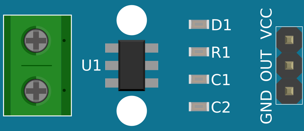
Pin Configuration and Descriptions

Pin Number Name Description
1 Vcc Power supply (4.5V to 5.5V)
2 GND Ground connection
3 OUT Analog output voltage
4 IP+ Current input
5 IP- Current output

Usage Instructions

How to Use the Component in a Circuit

  1. Connect the Vcc pin to a 5V power supply.
  2. Connect the GND pin to the ground of the power supply.
  3. Connect the IP+ and IP- pins in series with the load whose current you wish to measure.
  4. The OUT pin will output an analog voltage proportional to the current through the sensor.

Important Considerations and Best Practices

  • Ensure that the current does not exceed the rated maximum for the specific model of the ACS712 you are using (5A, 20A, or 30A).
  • The sensor is sensitive to magnetic fields; keep it away from magnets or wires carrying large currents.
  • Use bypass capacitors close to the power pins to minimize noise.
  • The output voltage is centered at Vcc/2 when no current is flowing through the sensor. This is typically 2.5V with a 5V supply.

Example Code for Arduino UNO

// ACS712 Current Sensor Example Code for Arduino UNO
const int analogIn = A0; // Connect the sensor output to analog pin A0
float sensitivity = 0.185; // Sensitivity for the 5A model (change as needed)
float offsetVoltage = 2.5; // Offset voltage for zero current (Vcc/2)

void setup() {
  Serial.begin(9600);
}

void loop() {
  float voltage = analogRead(analogIn) * (5.0 / 1023.0); // Convert analog reading to voltage
  float current = (voltage - offsetVoltage) / sensitivity; // Convert voltage to current
  Serial.print("Current: ");
  Serial.print(current, 3); // Print current with 3 decimal places
  Serial.println(" A");
  delay(1000); // Wait for 1 second before next reading
}

Troubleshooting and FAQs

Common Issues Users Might Face

  • Inaccurate Readings: Ensure that the sensor is properly calibrated, and the offset voltage is correctly set to Vcc/2.
  • No Output Voltage: Check the power supply connections and ensure that the sensor is not damaged.
  • Noise in the Signal: Use capacitors for filtering and keep the sensor away from high-current wires and magnetic fields.

Solutions and Tips for Troubleshooting

  • Calibrate the sensor by measuring the output voltage with no current flowing and adjust the offset voltage in the code accordingly.
  • Use twisted pair wires for the current leads to reduce electromagnetic interference.
  • Implement software filtering techniques like moving average to smooth out the signal.

FAQs

Q: Can the ACS712 sensor measure both AC and DC current? A: Yes, the ACS712 can measure both AC and DC currents.

Q: What is the accuracy of the ACS712 sensor? A: The accuracy can vary, but it is generally within a few percent of the actual current.

Q: How do I increase the resolution of my current measurements? A: Use a microcontroller with a higher resolution ADC or an external ADC with higher resolution.

Q: Is the ACS712 sensor isolated from the high current path? A: Yes, the sensor IC incorporates isolation to protect the electronics from high current paths.