How to Use Conector Anderson: Examples, Pinouts, and Specs
Introduction
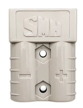
The Anderson Connector, manufactured by NADA with the part ID NENHUM, is a high-current connector designed for quick and reliable connections in power applications. It is widely used in electric vehicles, battery systems, solar power setups, and other high-current applications where secure and efficient power delivery is critical. Its robust design ensures durability and ease of use, making it a popular choice for both industrial and hobbyist projects.
Explore Projects Built with Conector Anderson


Explore Projects Built with Conector Anderson
Common Applications
- Electric vehicles (EVs) and charging systems
- Battery packs and power distribution systems
- Solar panel installations
- Uninterruptible Power Supplies (UPS)
- Robotics and high-power RC systems
Technical Specifications
The Anderson Connector is designed to handle high currents and voltages while maintaining a secure and reliable connection. Below are the key technical specifications:
| Parameter | Value |
|---|---|
| Manufacturer | NADA |
| Part ID | NENHUM |
| Maximum Current Rating | 50A, 120A, or 175A (varies by model) |
| Maximum Voltage Rating | 600V DC |
| Contact Material | Copper with silver plating |
| Housing Material | Polycarbonate (PC) |
| Operating Temperature | -20°C to +105°C |
| Connection Type | Genderless (hermaphroditic design) |
| Wire Size Compatibility | 6 AWG to 12 AWG (varies by model) |
Pin Configuration and Descriptions
The Anderson Connector features a genderless design, meaning both sides of the connector are identical and can mate with each other. Below is a description of the key components:
| Pin/Component | Description |
|---|---|
| Positive Terminal | Connects to the positive (+) side of the power source or load. |
| Negative Terminal | Connects to the negative (-) side of the power source or load. |
| Locking Mechanism | Ensures a secure connection and prevents accidental disconnection. |
| Housing | Provides insulation and mechanical protection for the terminals. |
Usage Instructions
How to Use the Anderson Connector in a Circuit
- Prepare the Wires: Strip the insulation from the wires to expose the appropriate length of conductor (based on the wire size and connector model).
- Crimp the Contacts: Use a compatible crimping tool to securely attach the connector contacts to the stripped wire ends.
- Insert Contacts into Housing: Push the crimped contacts into the connector housing until they click into place. Ensure proper polarity (positive and negative terminals).
- Connect the Mating Connectors: Align the connectors and push them together until the locking mechanism engages.
- Test the Connection: Verify the connection is secure and that there is no excessive resistance or heat buildup during operation.
Important Considerations and Best Practices
- Wire Selection: Use wires with the appropriate gauge (AWG) to handle the current rating of the connector.
- Crimping Tool: Always use a high-quality crimping tool designed for Anderson Connector contacts to ensure a reliable connection.
- Polarity: Double-check the polarity of the connections to avoid damage to the circuit or components.
- Environmental Protection: For outdoor or harsh environments, consider using additional protective measures such as weatherproof housings or covers.
- Mating and Unmating: Avoid excessive force when connecting or disconnecting the connectors to prevent damage to the housing or contacts.
Example: Connecting to an Arduino UNO
While the Anderson Connector is not directly used with low-power devices like the Arduino UNO, it can be part of a power distribution system that supplies power to the Arduino. Below is an example of how to integrate the Anderson Connector into a 12V power supply system for an Arduino project:
// Example Arduino code for a 12V power system using an Anderson Connector
// This code assumes the Arduino is powered via a 12V DC input connected
// through the Anderson Connector to a voltage regulator or power supply.

void setup() {
  // Initialize serial communication for debugging
  Serial.begin(9600);
  Serial.println("Arduino powered via Anderson Connector system.");
}

void loop() {
  // Example: Blink an LED to confirm the system is powered
  pinMode(13, OUTPUT); // Set pin 13 as output
  digitalWrite(13, HIGH); // Turn on the LED
  delay(1000); // Wait for 1 second
  digitalWrite(13, LOW); // Turn off the LED
  delay(1000); // Wait for 1 second
}
Troubleshooting and FAQs
Common Issues and Solutions
| Issue | Solution |
|---|---|
| Connector does not lock securely | Ensure the contacts are fully inserted into the housing and the locking mechanism is not damaged. |
| Overheating during operation | Check for loose connections, undersized wires, or excessive current draw. |
| Difficulty crimping contacts | Use a high-quality crimping tool designed for the specific connector model. |
| Incorrect polarity | Double-check the wiring and ensure the positive and negative terminals are correctly connected. |
| Connector is difficult to mate/unmate | Inspect for debris or damage in the housing and clean or replace as necessary. |
FAQs
Can the Anderson Connector handle AC power? Yes, the Anderson Connector can handle both DC and AC power, provided the voltage and current ratings are not exceeded.
Are Anderson Connectors waterproof? Standard Anderson Connectors are not waterproof. For outdoor or wet environments, use additional protective measures such as weatherproof housings.
Can I use the Anderson Connector for low-current applications? While designed for high-current applications, the Anderson Connector can be used for low-current systems as long as the wire size and crimping are appropriate.
How do I disconnect the connectors? To disconnect, press the locking mechanism (if present) and pull the connectors apart. Avoid excessive force to prevent damage.
By following this documentation, users can confidently integrate the Anderson Connector into their power systems for reliable and efficient performance.