How to Use 12V PWM 80x80mm Fan: Examples, Pinouts, and Specs
Introduction
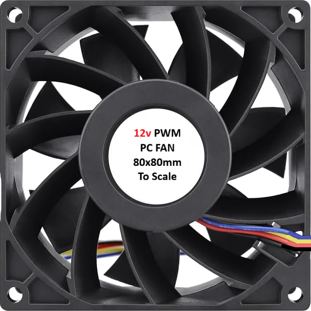
The 12V PWM 80x80mm Fan is a compact and efficient cooling solution designed for a variety of applications. With its 80x80mm size, it is ideal for use in computer systems, power supplies, and other electronic devices requiring effective heat dissipation. The fan features pulse-width modulation (PWM) control, enabling variable speed operation to optimize airflow, reduce noise, and minimize power consumption. This makes it a versatile and energy-efficient choice for thermal management.
Explore Projects Built with 12V PWM 80x80mm Fan
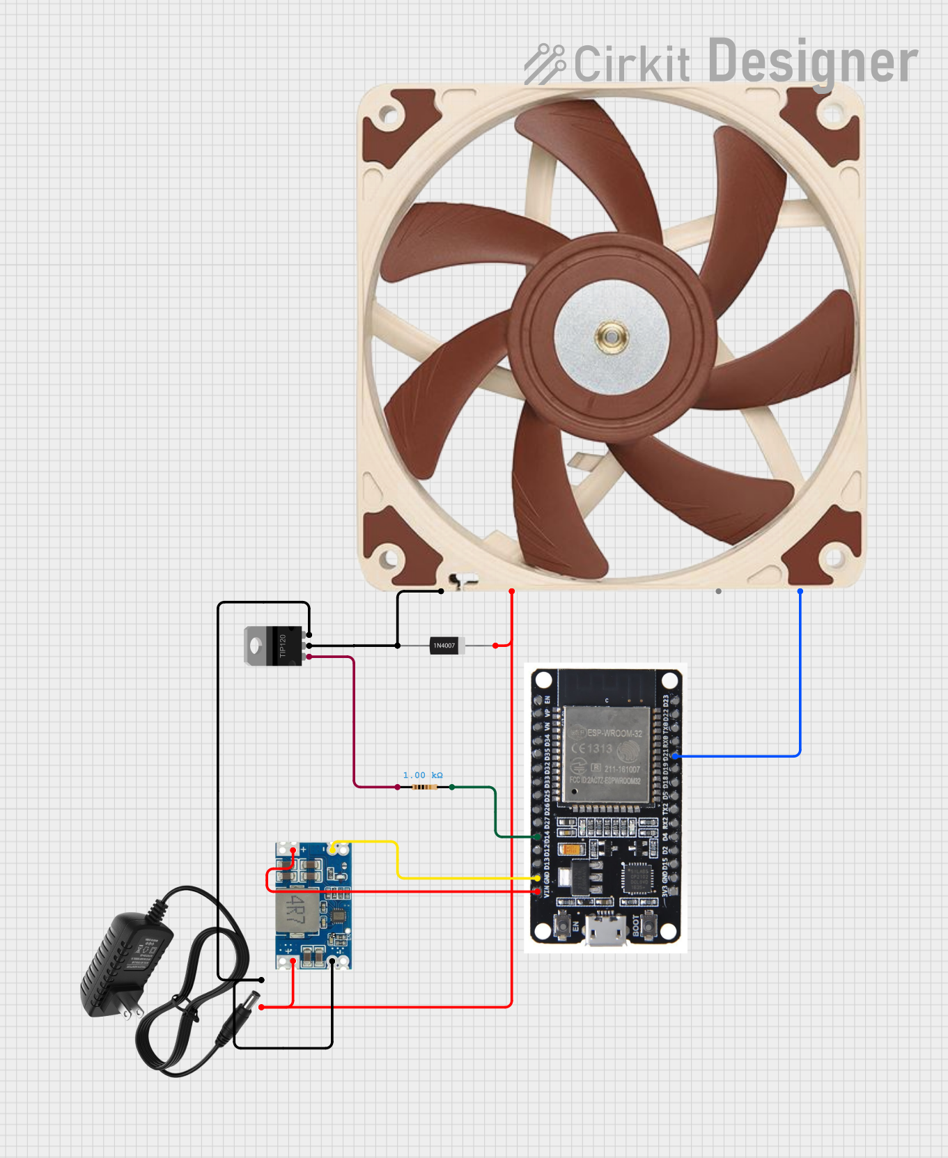


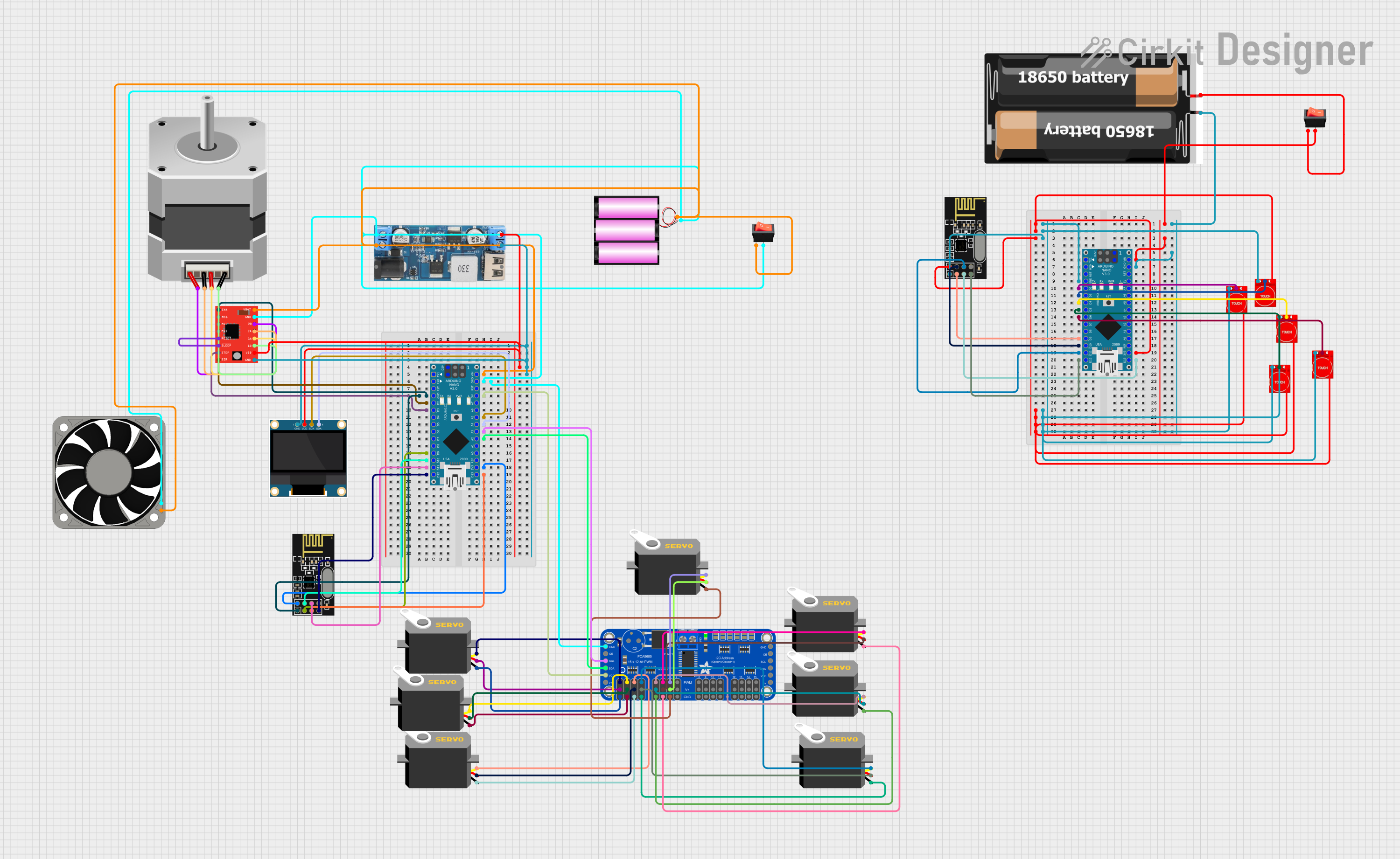
Explore Projects Built with 12V PWM 80x80mm Fan
Common Applications and Use Cases
- Cooling for desktop computers, servers, and gaming systems
- Heat dissipation in power supplies and industrial equipment
- Ventilation in 3D printers and other compact electronic devices
- Custom cooling solutions for DIY electronics projects
Technical Specifications
Below are the key technical details and pin configuration for the 12V PWM 80x80mm Fan:
Key Technical Details
| Parameter | Specification |
|---|---|
| Operating Voltage | 12V DC |
| Current Rating | 0.15A to 0.30A (varies by model) |
| Power Consumption | 1.8W to 3.6W |
| Fan Dimensions | 80mm x 80mm x 25mm |
| Airflow | 30-50 CFM (Cubic Feet per Minute) |
| Speed Range | 800-3000 RPM (PWM controlled) |
| Noise Level | 20-35 dBA (depending on speed) |
| Connector Type | 4-pin PWM connector |
| Bearing Type | Sleeve or ball bearing |
| Operating Temperature | -10°C to 70°C |
| Lifespan | 30,000 to 50,000 hours |
Pin Configuration and Descriptions
The fan uses a standard 4-pin PWM connector. The pinout is as follows:
| Pin Number | Name | Description |
|---|---|---|
| 1 | GND | Ground connection for the fan |
| 2 | VCC | Power supply input (12V DC) |
| 3 | Tachometer | Outputs a signal for monitoring fan speed (RPM) |
| 4 | PWM Control | Accepts a PWM signal (typically 25kHz) to control fan speed (duty cycle) |
Usage Instructions
How to Use the Component in a Circuit
- Power Connection: Connect the VCC pin to a 12V DC power source and the GND pin to ground.
- PWM Control: Use a microcontroller (e.g., Arduino) or a dedicated PWM controller to send a PWM signal to the PWM Control pin. The duty cycle of the PWM signal determines the fan speed:
- 0% duty cycle: Fan is off
- 50% duty cycle: Fan runs at approximately half speed
- 100% duty cycle: Fan runs at full speed
- Tachometer Monitoring: If needed, connect the Tachometer pin to a microcontroller input pin to monitor the fan's RPM. The tachometer typically outputs two pulses per revolution.
Important Considerations and Best Practices
- PWM Signal Frequency: Ensure the PWM signal frequency is around 25kHz for optimal performance.
- Power Supply: Use a stable 12V DC power source to avoid damaging the fan.
- Mounting: Secure the fan using screws or clips to minimize vibration and noise.
- Airflow Direction: Check the fan's airflow direction (usually indicated by arrows on the fan housing) to ensure proper cooling.
- Avoid Blockages: Keep the fan's intake and exhaust areas clear of obstructions for maximum airflow.
Example: Connecting to an Arduino UNO
Below is an example of how to control the fan speed using an Arduino UNO:
// Define the PWM pin connected to the fan's PWM control pin
const int pwmPin = 9;

void setup() {
  // Set the PWM pin as an output
  pinMode(pwmPin, OUTPUT);
}

void loop() {
  // Example: Gradually increase fan speed from 0% to 100%
  for (int dutyCycle = 0; dutyCycle <= 255; dutyCycle += 5) {
    analogWrite(pwmPin, dutyCycle); // Write PWM signal to the fan
    delay(50); // Wait 50ms before increasing the duty cycle
  }

  // Example: Gradually decrease fan speed from 100% to 0%
  for (int dutyCycle = 255; dutyCycle >= 0; dutyCycle -= 5) {
    analogWrite(pwmPin, dutyCycle); // Write PWM signal to the fan
    delay(50); // Wait 50ms before decreasing the duty cycle
  }
}
Notes:
- The
analogWrite()function generates a PWM signal on the specified pin. - Ensure the Arduino's PWM pin is connected to the fan's PWM Control pin.
Troubleshooting and FAQs
Common Issues and Solutions
Fan Does Not Spin
- Cause: No power or incorrect wiring.
- Solution: Verify the VCC and GND connections. Ensure the power supply provides 12V DC.
Fan Runs at Full Speed Constantly
- Cause: PWM signal not connected or incorrect frequency.
- Solution: Check the PWM Control pin connection. Ensure the PWM signal frequency is around 25kHz.
Fan Speed Does Not Change
- Cause: Incorrect PWM duty cycle or faulty PWM signal.
- Solution: Verify the PWM signal using an oscilloscope. Ensure the duty cycle is within the 0-100% range.
Excessive Noise or Vibration
- Cause: Loose mounting or obstructed airflow.
- Solution: Secure the fan properly and clear any obstructions near the fan.
Tachometer Signal Not Detected
- Cause: Incorrect connection or incompatible microcontroller input.
- Solution: Verify the Tachometer pin connection. Ensure the microcontroller input pin is configured correctly.
FAQs
Q: Can I use a 5V PWM signal to control the fan?
A: Yes, most 12V PWM fans are compatible with 5V PWM signals. However, check the fan's datasheet to confirm compatibility.
Q: What happens if I don't connect the PWM Control pin?
A: The fan will typically run at full speed by default if the PWM Control pin is left unconnected.
Q: Can I use this fan with a 3-pin connector?
A: Yes, but you will lose PWM speed control. The fan will run at full speed when powered.
Q: How do I clean the fan?
A: Use compressed air to remove dust. Avoid using liquids or disassembling the fan.
This concludes the documentation for the 12V PWM 80x80mm Fan.