How to Use Castle Creations CC BEC 2.0: Examples, Pinouts, and Specs
Introduction
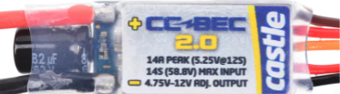
The Castle Creations CC BEC 2.0 is a high-performance battery eliminator circuit (BEC) designed to provide a stable and adjustable voltage output for powering servos, receivers, and other electronics in remote control (RC) applications. By eliminating the need for a separate receiver battery, the CC BEC 2.0 simplifies power management and reduces the overall weight of RC systems. It is particularly well-suited for high-power setups where consistent and reliable power delivery is critical.
Explore Projects Built with Castle Creations CC BEC 2.0
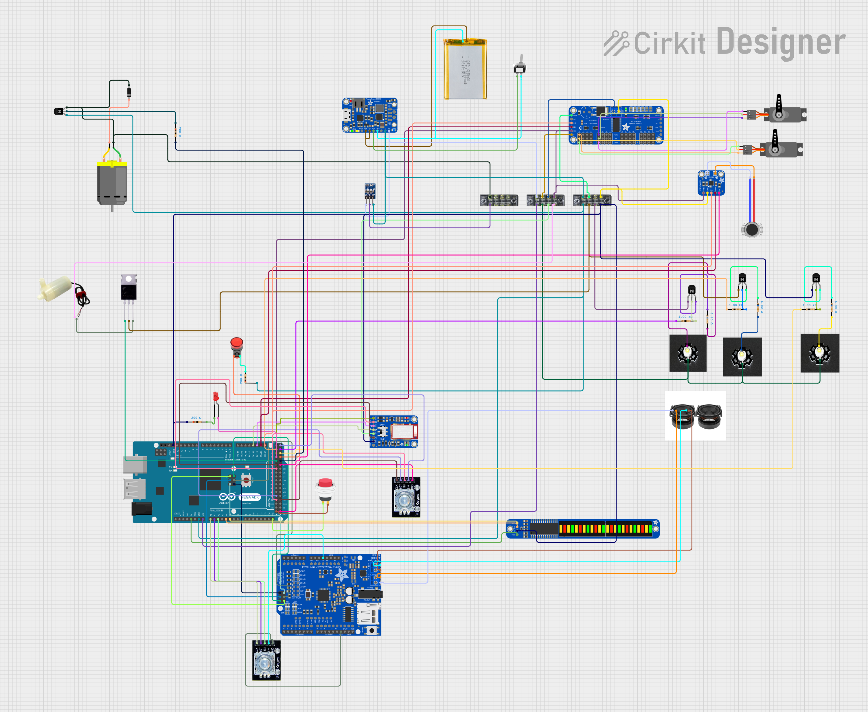


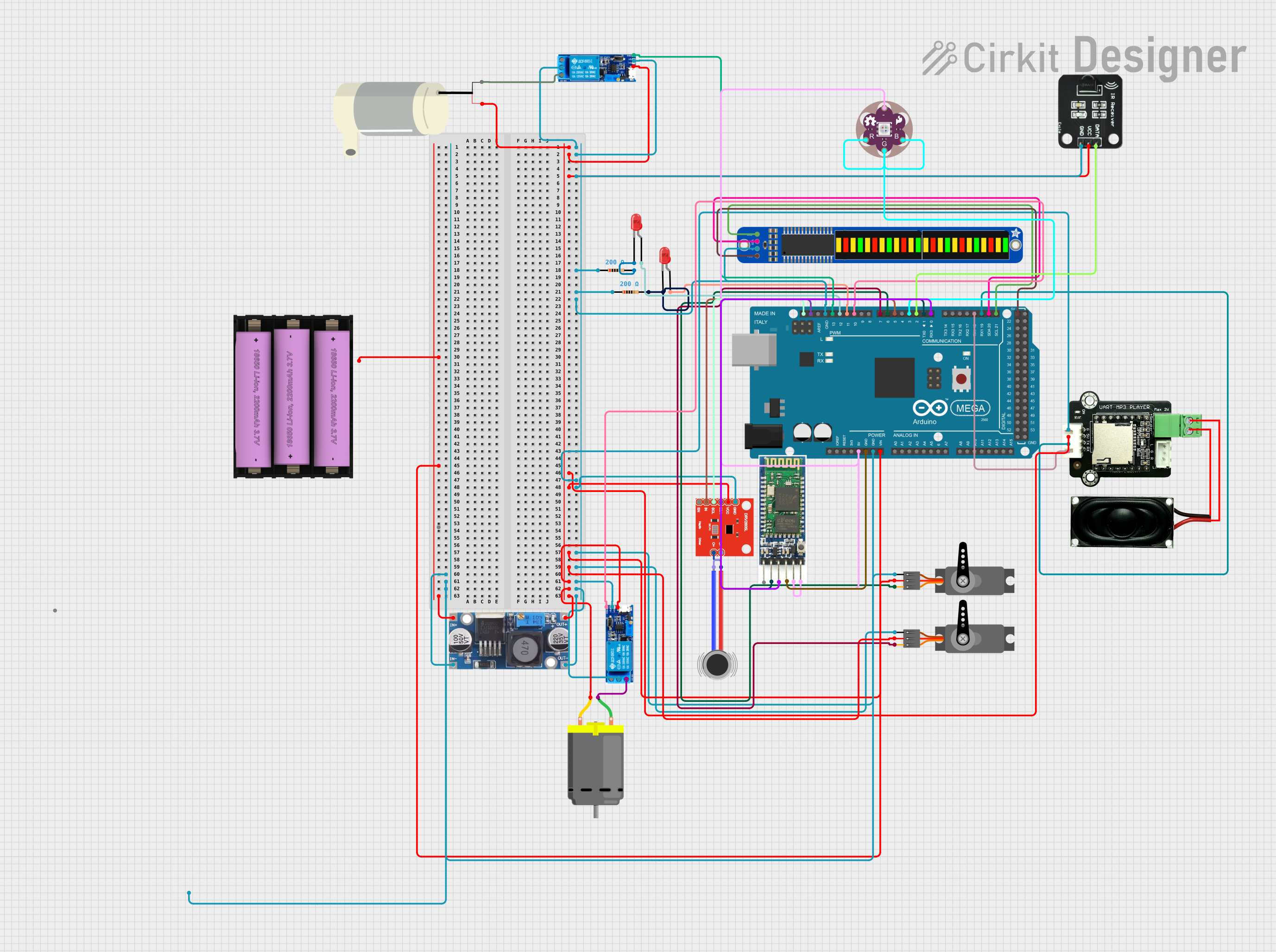
Explore Projects Built with Castle Creations CC BEC 2.0
Common Applications and Use Cases
- RC airplanes, helicopters, cars, and boats
- Powering servos and receivers in high-current systems
- Providing stable voltage for FPV (First-Person View) equipment
- Applications requiring adjustable voltage output for sensitive electronics
Technical Specifications
The CC BEC 2.0 is available in two variants: Standard and High Voltage (HV). Below are the key specifications for both models:
| Specification | Standard Version | High Voltage (HV) Version |
|---|---|---|
| Input Voltage Range | 2S to 6S LiPo (8V–25.2V) | 2S to 12S LiPo (8V–50.4V) |
| Output Voltage Range | 4.75V to 12V (adjustable) | 4.75V to 14V (adjustable) |
| Maximum Continuous Current | 15A | 15A |
| Peak Current (2 seconds) | 20A | 20A |
| Efficiency | Up to 90% | Up to 90% |
| Dimensions | 1.69" x 1.3" x 0.94" | 1.69" x 1.3" x 0.94" |
| Weight | 0.9 oz (25.5 g) | 0.9 oz (25.5 g) |
Pin Configuration and Descriptions
The CC BEC 2.0 has a simple wiring interface for easy integration into RC systems. Below is the pin configuration:
| Pin/Wire Color | Description |
|---|---|
| Red Wire | Positive output voltage (VOUT) |
| Black Wire | Ground (GND) |
| Yellow Wire | Signal wire for programming (optional) |
| Input Wires | Two thicker wires for battery input (polarity marked) |
Usage Instructions
How to Use the CC BEC 2.0 in a Circuit
- Connect the Input Wires: Attach the input wires to the main battery pack of your RC system. Ensure correct polarity (positive and negative terminals are clearly marked).
- Connect the Output Wires: Connect the red (positive) and black (ground) output wires to the receiver or other electronics requiring power.
- Adjust the Output Voltage (if necessary):
- Use the Castle Link USB programming kit or a Castle Field Link card to adjust the output voltage.
- Connect the yellow signal wire to the programming device and follow the manufacturer's software instructions.
- Secure the BEC: Mount the CC BEC 2.0 securely in your RC vehicle using double-sided tape or zip ties to prevent movement during operation.
Important Considerations and Best Practices
- Voltage Compatibility: Ensure the output voltage is compatible with the connected electronics to avoid damage.
- Heat Dissipation: The CC BEC 2.0 is highly efficient, but it may generate heat under high loads. Install it in a location with adequate airflow.
- Current Limits: Do not exceed the maximum continuous current rating of 15A to prevent overheating or damage.
- Programming: Use the Castle Link software to fine-tune the output voltage and other settings for optimal performance.
Example: Connecting to an Arduino UNO
The CC BEC 2.0 can be used to power an Arduino UNO in projects requiring a stable voltage source. Below is an example of how to connect it:
- Set the output voltage of the CC BEC 2.0 to 5V using the Castle Link software.
- Connect the red wire (VOUT) to the Arduino's 5V pin.
- Connect the black wire (GND) to the Arduino's GND pin.
// Example Arduino code to test power delivery from the CC BEC 2.0
void setup() {
  pinMode(LED_BUILTIN, OUTPUT); // Set the built-in LED pin as an output
}

void loop() {
  digitalWrite(LED_BUILTIN, HIGH); // Turn the LED on
  delay(1000);                     // Wait for 1 second
  digitalWrite(LED_BUILTIN, LOW);  // Turn the LED off
  delay(1000);                     // Wait for 1 second
}
Troubleshooting and FAQs
Common Issues and Solutions
BEC Overheating:
- Cause: Exceeding the maximum current rating or poor airflow.
- Solution: Reduce the load on the BEC or improve ventilation around the component.
Output Voltage Not Stable:
- Cause: Incorrect input voltage or damaged wiring.
- Solution: Verify the input voltage is within the specified range and check all connections for damage or loose wires.
Receiver or Servos Not Powering On:
- Cause: Incorrect output voltage setting or wiring issue.
- Solution: Use the Castle Link software to confirm the output voltage is set correctly. Double-check all connections.
Programming Issues:
- Cause: Yellow signal wire not connected properly to the programming device.
- Solution: Ensure the yellow wire is securely connected to the Castle Link or Field Link device and follow the software instructions.
FAQs
Q: Can I use the CC BEC 2.0 with a 3S LiPo battery?
A: Yes, both the Standard and HV versions support 3S LiPo batteries. Ensure the input voltage is within the specified range.
Q: How do I know if the BEC is overheating?
A: The BEC may shut down or reduce output power if it overheats. Check for excessive heat during operation and ensure proper airflow.
Q: Can I power multiple servos with the CC BEC 2.0?
A: Yes, as long as the total current draw does not exceed the maximum continuous current rating of 15A.
Q: Is the CC BEC 2.0 waterproof?
A: No, the CC BEC 2.0 is not waterproof. Protect it from water exposure to avoid damage.
By following this documentation, users can effectively integrate the Castle Creations CC BEC 2.0 into their RC systems for reliable and efficient power management.