
How to Use A4988 Stepper Motor Driver Carrier: Examples, Pinouts, and Specs
 Design with A4988 Stepper Motor Driver Carrier in Cirkit Designer
Introduction
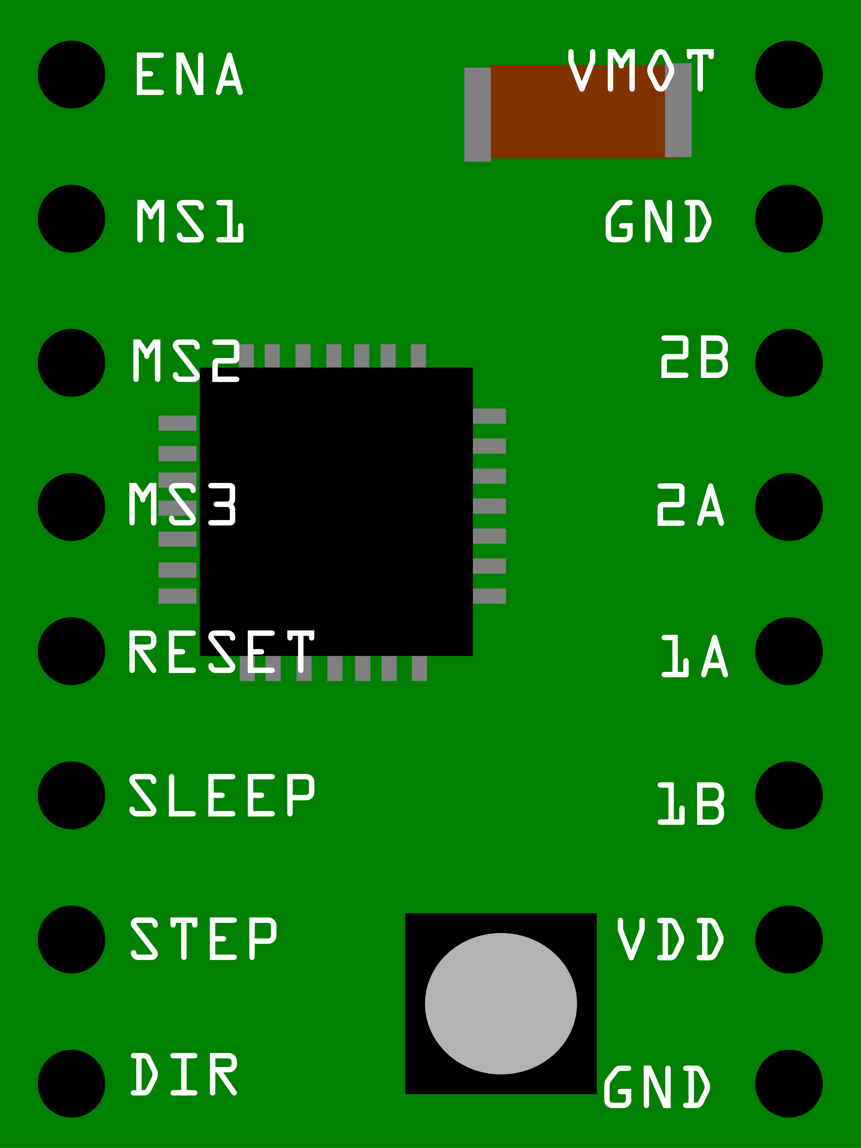
The A4988 is a microstepping driver designed for controlling bipolar stepper motors. It enables precise control of motor position and speed, making it ideal for applications requiring high accuracy and smooth motion. The A4988 features adjustable current control, over-temperature protection, and a built-in translator, simplifying its integration with microcontrollers. This component is widely used in 3D printers, CNC machines, robotics, and other motion control systems.
Explore Projects Built with A4988 Stepper Motor Driver Carrier
 Open Project in Cirkit Designer
 Open Project in Cirkit Designer
 Open Project in Cirkit Designer
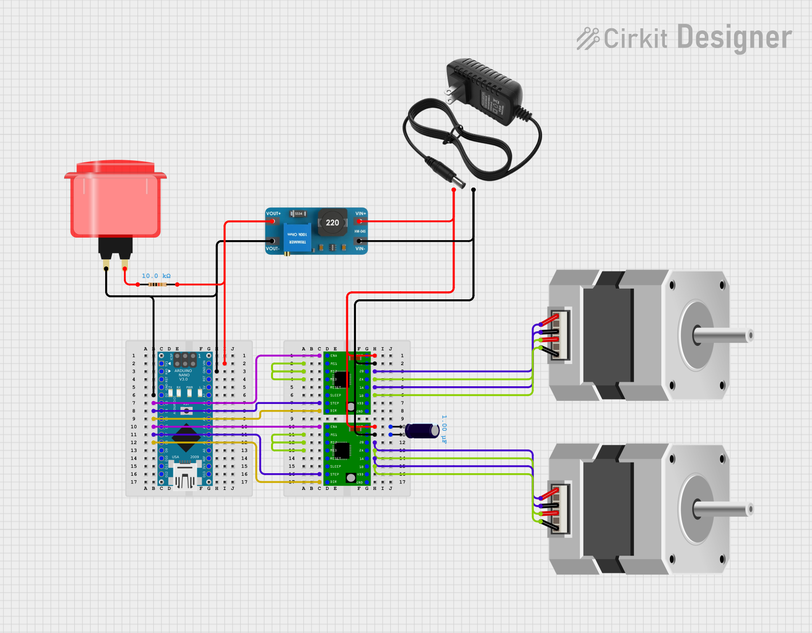 Open Project in Cirkit Designer
Explore Projects Built with A4988 Stepper Motor Driver Carrier
Open Project in Cirkit DesignerOpen Project in Cirkit DesignerOpen Project in Cirkit DesignerOpen Project in Cirkit DesignerCommon Applications
- 3D printers for precise layer positioning
- CNC machines for accurate tool movement
- Robotics for smooth and controlled motion
- Automated systems requiring stepper motor control
Technical Specifications
Key Technical Details
- Operating Voltage (VMOT): 8 V to 35 V
- Logic Voltage (VDD): 3.3 V to 5 V
- Maximum Output Current: 2 A per coil (with sufficient cooling)
- Microstepping Modes: Full, 1/2, 1/4, 1/8, and 1/16 steps
- Current Control: Adjustable via potentiometer
- Protection Features: Over-temperature, over-current, and under-voltage lockout
- Built-in Translator: Simplifies step and direction control
- Dimensions: 20 mm × 15 mm × 11 mm (approx.)
Pin Configuration and Descriptions
The A4988 has 16 pins, which are described in the table below:
| Pin Name | Type | Description |
|---|---|---|
| VMOT | Power Input | Motor power supply (8 V to 35 V). Connect to the stepper motor power source. |
| GND | Power Ground | Ground connection for motor power supply. |
| VDD | Power Input | Logic voltage supply (3.3 V to 5 V). |
| GND | Power Ground | Ground connection for logic voltage supply. |
| 1A, 1B | Motor Output | Connect to one coil of the stepper motor. |
| 2A, 2B | Motor Output | Connect to the other coil of the stepper motor. |
| STEP | Logic Input | Receives step pulses to control motor movement. |
| DIR | Logic Input | Sets the direction of motor rotation. |
| ENABLE | Logic Input | Enables or disables the motor driver (active low). |
| MS1, MS2, MS3 | Logic Input | Microstepping mode selection pins. |
| RESET | Logic Input | Resets the driver (active low). |
| SLEEP | Logic Input | Puts the driver into low-power sleep mode (active low). |
| REF | Analog Input | Reference voltage for current control. Adjusted via the onboard potentiometer. |
| FAULT | Logic Output | Indicates fault conditions (e.g., over-temperature). |
Usage Instructions
Connecting the A4988 to a Circuit
- Power Supply:
- Connect VMOT and GND to the motor power supply (8 V to 35 V).
- Connect VDD and GND to the logic power supply (3.3 V or 5 V).
- Motor Connections:
- Connect the stepper motor coils to 1A, 1B, 2A, and 2B. Ensure the correct pairing of coils.
- Control Pins:
- Connect STEP and DIR to the microcontroller's digital output pins.
- Use ENABLE to enable or disable the driver as needed.
- Microstepping Configuration:
- Set MS1, MS2, and MS3 to HIGH or LOW to select the desired microstepping mode:
- Full step: MS1 = LOW, MS2 = LOW, MS3 = LOW
- 1/2 step: MS1 = HIGH, MS2 = LOW, MS3 = LOW
- 1/4 step: MS1 = LOW, MS2 = HIGH, MS3 = LOW
- 1/8 step: MS1 = HIGH, MS2 = HIGH, MS3 = LOW
- 1/16 step: MS1 = HIGH, MS2 = HIGH, MS3 = HIGH
- Set MS1, MS2, and MS3 to HIGH or LOW to select the desired microstepping mode:
- Adjusting Current Limit:
- Use the onboard potentiometer to set the current limit. Measure the voltage at the REF pin and calculate the current limit using the formula:
where RS is the sense resistor value (typically 0.1 Ω).Current Limit = VREF / (8 × RS)
- Use the onboard potentiometer to set the current limit. Measure the voltage at the REF pin and calculate the current limit using the formula:
Example Arduino Code
Below is an example of how to control a stepper motor using the A4988 and an Arduino UNO:
// Define control pins for the A4988 driver
#define STEP_PIN 3  // Pin connected to STEP
#define DIR_PIN 4   // Pin connected to DIR

void setup() {
  pinMode(STEP_PIN, OUTPUT); // Set STEP pin as output
  pinMode(DIR_PIN, OUTPUT);  // Set DIR pin as output

  digitalWrite(DIR_PIN, HIGH); // Set initial direction (HIGH = clockwise)
}

void loop() {
  // Generate step pulses to move the motor
  digitalWrite(STEP_PIN, HIGH); // Step pulse HIGH
  delayMicroseconds(1000);      // Wait 1 ms
  digitalWrite(STEP_PIN, LOW);  // Step pulse LOW
  delayMicroseconds(1000);      // Wait 1 ms
}
Best Practices
- Use a heat sink or active cooling if driving the motor at high currents.
- Avoid connecting or disconnecting the motor while the driver is powered to prevent damage.
- Ensure proper decoupling capacitors are placed near VMOT and VDD to reduce noise.
- Use a multimeter to verify connections and current settings before powering the circuit.
Troubleshooting and FAQs
Common Issues and Solutions
Motor Not Moving:
- Verify power supply connections and ensure VMOT and VDD are within the specified range.
- Check the STEP and DIR signals from the microcontroller.
- Ensure the motor coils are correctly connected to 1A, 1B, 2A, and 2B.
Overheating Driver:
- Reduce the current limit using the potentiometer.
- Add a heat sink or active cooling to the driver.
Erratic Motor Movement:
- Check for loose or incorrect wiring.
- Ensure proper grounding between the driver and microcontroller.
- Verify the microstepping mode configuration (MS1, MS2, MS3).
FAULT Pin Active:
- Check for over-temperature or over-current conditions.
- Allow the driver to cool down and reduce the current limit if necessary.
FAQs
Q: Can the A4988 drive unipolar stepper motors?
A: No, the A4988 is designed for bipolar stepper motors only.
Q: How do I calculate the VREF voltage for a specific current limit?
A: Use the formula VREF = Current Limit × 8 × RS. For example, for a 1 A current limit and RS = 0.1 Ω, VREF = 0.8 V.
Q: What happens if I don't connect the ENABLE pin?
A: The ENABLE pin defaults to active (LOW), so the driver will be enabled unless explicitly set HIGH.
Q: Can I use the A4988 with a 12 V power supply?
A: Yes, the A4988 supports motor power supplies between 8 V and 35 V, so 12 V is within the acceptable range.