
How to Use ESP32 DevKit V1 (30-pin): Examples, Pinouts, and Specs
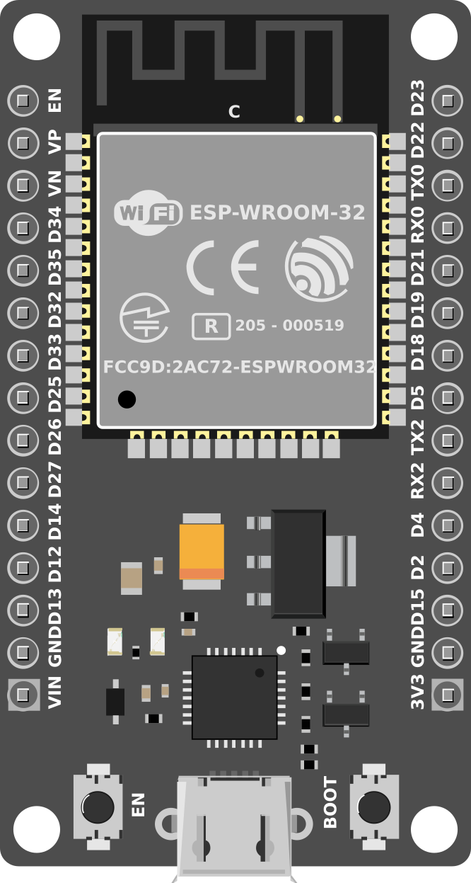
 Design with ESP32 DevKit V1 (30-pin) in Cirkit Designer
Introduction
The ESP32 DevKit V1 (30-pin) is a versatile development board based on the ESP32 chip, which integrates Wi-Fi and Bluetooth capabilities. This board is designed for IoT (Internet of Things) applications, prototyping, and other embedded systems projects. With its 30 GPIO pins, ADC (Analog-to-Digital Converter), PWM, and communication interfaces, the ESP32 DevKit V1 is a powerful tool for developers and hobbyists alike.
Explore Projects Built with ESP32 DevKit V1 (30-pin)
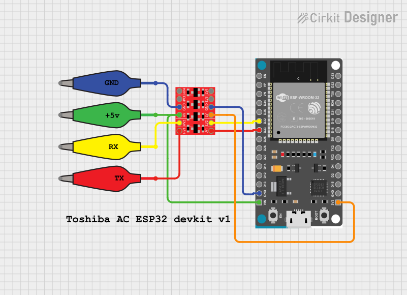 Open Project in Cirkit Designer
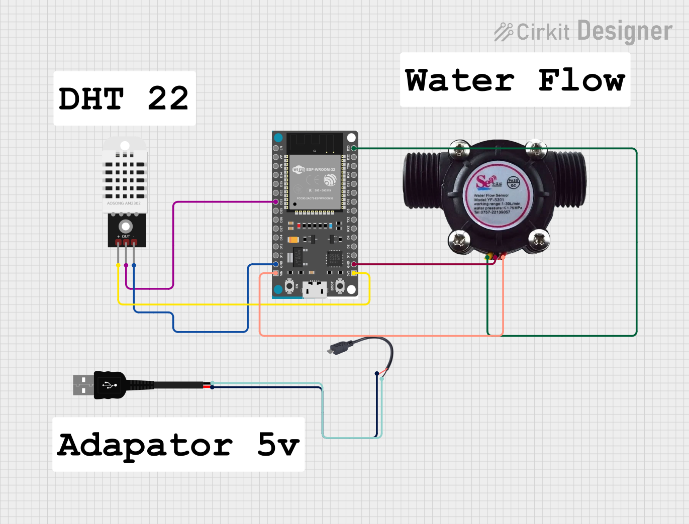 Open Project in Cirkit Designer
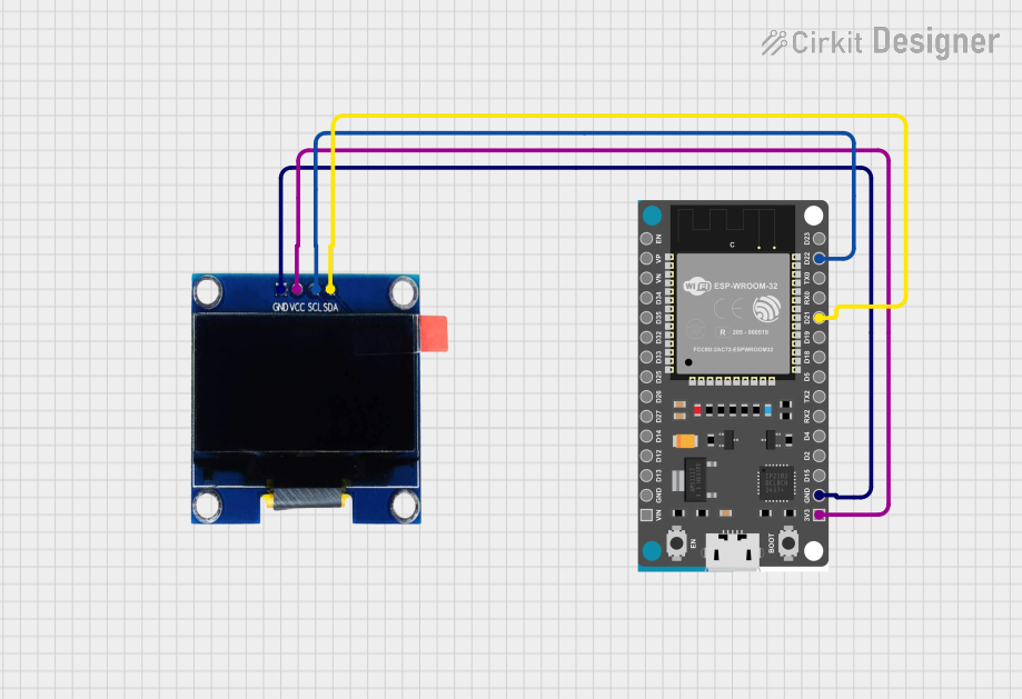 Open Project in Cirkit Designer
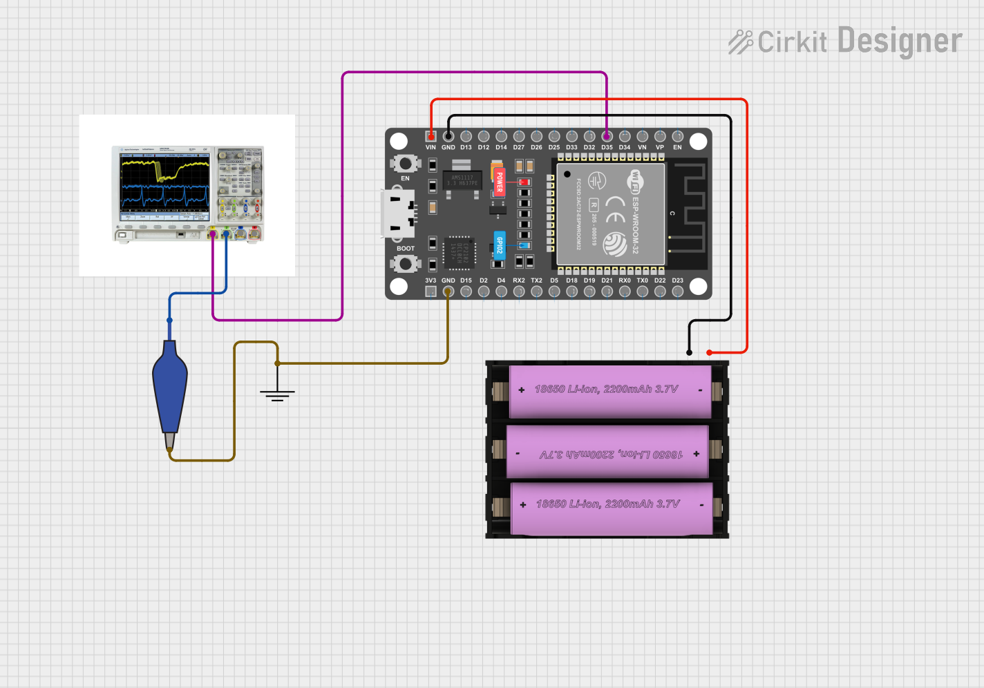 Open Project in Cirkit Designer
Explore Projects Built with ESP32 DevKit V1 (30-pin)
Open Project in Cirkit DesignerOpen Project in Cirkit DesignerOpen Project in Cirkit DesignerOpen Project in Cirkit DesignerCommon Applications
- IoT devices and smart home automation
- Wireless sensor networks
- Robotics and control systems
- Data logging and monitoring
- Prototyping for Bluetooth and Wi-Fi-enabled devices
Technical Specifications
The ESP32 DevKit V1 (30-pin) is built around the ESP32-WROOM-32 module, which features a dual-core processor and integrated wireless connectivity. Below are the key technical details:
Key Specifications
| Specification | Value |
|---|---|
| Microcontroller | ESP32-WROOM-32 |
| CPU | Dual-core Xtensa® 32-bit LX6 @ 240 MHz |
| Flash Memory | 4 MB |
| SRAM | 520 KB |
| Wi-Fi | 802.11 b/g/n (2.4 GHz) |
| Bluetooth | v4.2 BR/EDR and BLE |
| Operating Voltage | 3.3V |
| Input Voltage (VIN) | 5V (via USB or VIN pin) |
| GPIO Pins | 30 |
| ADC Channels | 18 (12-bit resolution) |
| PWM Channels | 16 |
| Communication Interfaces | UART, SPI, I2C, I2S, CAN, Ethernet MAC |
| Power Consumption | Ultra-low power (varies by mode) |
| Dimensions | 51 mm x 25.4 mm |
Pin Configuration
The ESP32 DevKit V1 has 30 pins, each with specific functions. Below is the pinout description:
| Pin Number | Pin Name | Functionality |
|---|---|---|
| 1 | EN | Enable pin (active high) |
| 2 | IO23 | GPIO23, SPI MOSI |
| 3 | IO22 | GPIO22, I2C SCL |
| 4 | IO21 | GPIO21, I2C SDA |
| 5 | GND | Ground |
| 6 | VIN | Input voltage (5V) |
| 7 | IO19 | GPIO19, SPI MISO |
| 8 | IO18 | GPIO18, SPI SCK |
| 9 | IO17 | GPIO17 |
| 10 | IO16 | GPIO16 |
| 11 | IO15 | GPIO15, PWM, ADC |
| 12 | IO14 | GPIO14, PWM, ADC |
| 13 | IO13 | GPIO13, PWM, ADC |
| 14 | IO12 | GPIO12, PWM, ADC |
| 15 | GND | Ground |
| 16 | IO11 | GPIO11 |
| 17 | IO10 | GPIO10 |
| 18 | IO9 | GPIO9 |
| 19 | IO8 | GPIO8 |
| 20 | IO7 | GPIO7 |
| 21 | IO6 | GPIO6 |
| 22 | IO5 | GPIO5, PWM, ADC |
| 23 | IO4 | GPIO4, PWM, ADC |
| 24 | IO3 | GPIO3, UART RX |
| 25 | IO2 | GPIO2, PWM, ADC |
| 26 | IO1 | GPIO1, UART TX |
| 27 | IO0 | GPIO0, Boot Mode Selection |
| 28 | 3V3 | 3.3V Output |
| 29 | GND | Ground |
| 30 | IO25 | GPIO25, PWM, ADC |
Usage Instructions
Using the ESP32 DevKit V1 in a Circuit
Powering the Board:
- Connect the board to your computer via a micro-USB cable for power and programming.
- Alternatively, supply 5V to the VIN pin or 3.3V to the 3V3 pin.
Programming the Board:
- Install the Arduino IDE and add the ESP32 board package via the Board Manager.
- Select "ESP32 Dev Module" as the board type in the Arduino IDE.
- Connect the board to your computer and select the appropriate COM port.
Connecting Peripherals:
- Use the GPIO pins for digital and analog input/output.
- Connect sensors, actuators, or communication modules as needed.
- Ensure proper voltage levels (3.3V logic) to avoid damaging the board.
Example Code: Blinking an LED
Below is an example of how to blink an LED connected to GPIO2:
// Define the GPIO pin for the LED
#define LED_PIN 2

void setup() {
  pinMode(LED_PIN, OUTPUT); // Set GPIO2 as an output pin
}

void loop() {
  digitalWrite(LED_PIN, HIGH); // Turn the LED on
  delay(1000);                 // Wait for 1 second
  digitalWrite(LED_PIN, LOW);  // Turn the LED off
  delay(1000);                 // Wait for 1 second
}
Important Considerations
- Voltage Levels: The ESP32 operates at 3.3V logic. Avoid connecting 5V signals directly to GPIO pins.
- Boot Mode: GPIO0 is used for boot mode selection. Avoid pulling it high during startup unless necessary.
- Power Supply: Ensure a stable power supply to avoid unexpected resets or malfunctions.
Troubleshooting and FAQs
Common Issues
The board is not detected by the computer:
- Ensure the USB cable is functional and supports data transfer.
- Install the correct USB-to-serial driver (e.g., CP2102 or CH340).
Upload errors in Arduino IDE:
- Check the selected COM port and board type in the Arduino IDE.
- Press and hold the "BOOT" button on the board while uploading the code.
Wi-Fi connection issues:
- Verify the SSID and password in your code.
- Ensure the router is operating on the 2.4 GHz band (ESP32 does not support 5 GHz).
FAQs
Q: Can I power the ESP32 DevKit V1 with a battery?
A: Yes, you can use a 3.7V LiPo battery connected to the 3V3 pin or a 5V source connected to the VIN pin.
Q: How many devices can the ESP32 connect to via Bluetooth?
A: The ESP32 supports up to 7 simultaneous Bluetooth connections in BLE mode.
Q: Can I use the ESP32 DevKit V1 for deep sleep applications?
A: Yes, the ESP32 supports ultra-low-power deep sleep modes, making it ideal for battery-powered projects.
Q: What is the maximum current draw of the ESP32?
A: The ESP32 can draw up to 240 mA during peak operation (e.g., Wi-Fi transmission). Ensure your power supply can handle this.