How to Use DC-DC Convertor: Examples, Pinouts, and Specs
Introduction
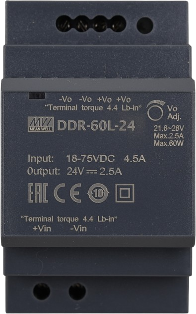
A DC-DC converter is an electronic circuit that converts direct current (DC) from one voltage level to another, enabling efficient power management in a wide range of applications. The DDR-60L-24 is a high-performance DC-DC converter designed for industrial, automotive, and embedded systems. It ensures stable voltage output, high efficiency, and reliable operation in demanding environments.
Explore Projects Built with DC-DC Convertor


Explore Projects Built with DC-DC Convertor
Common Applications and Use Cases
- Powering embedded systems and microcontrollers
- Voltage regulation in industrial automation
- Battery-powered devices and systems
- Renewable energy systems (e.g., solar panels)
- Automotive electronics for voltage conversion
Technical Specifications
Key Technical Details
| Parameter | Value |
|---|---|
| Input Voltage Range | 9V to 36V DC |
| Output Voltage | 24V DC |
| Output Current | 2.5A |
| Output Power | 60W |
| Efficiency | Up to 92% |
| Operating Temperature | -40°C to +85°C |
| Protection Features | Overload, Overvoltage, Short Circuit |
| Dimensions | 100mm x 32mm x 85mm |
| Weight | 300g |
| Mounting Type | DIN Rail |
Pin Configuration and Descriptions
| Pin Number | Name | Description |
|---|---|---|
| 1 | +V Input | Positive input voltage terminal |
| 2 | -V Input | Negative input voltage terminal (GND) |
| 3 | +V Output | Positive output voltage terminal |
| 4 | -V Output | Negative output voltage terminal (GND) |
Usage Instructions
How to Use the Component in a Circuit
- Input Voltage Connection: Connect the input voltage source (9V to 36V DC) to the
+V Inputand-V Inputterminals. Ensure the input voltage is within the specified range to avoid damage. - Output Voltage Connection: Connect the load to the
+V Outputand-V Outputterminals. The output voltage will be regulated to 24V DC. - Mounting: Secure the DDR-60L-24 to a DIN rail for stable installation in industrial environments.
- Power On: Once all connections are secure, power on the input source. The converter will regulate the output voltage automatically.
Important Considerations and Best Practices
- Input Voltage Range: Ensure the input voltage remains within the 9V to 36V range to prevent damage to the converter.
- Load Requirements: Do not exceed the maximum output current of 2.5A or the power rating of 60W.
- Heat Dissipation: Install the converter in a well-ventilated area to prevent overheating. Use additional cooling if necessary in high-temperature environments.
- Polarity: Double-check the polarity of the input and output connections to avoid reverse polarity damage.
- Protection Features: The DDR-60L-24 includes overload, overvoltage, and short-circuit protection. However, avoid intentionally triggering these protections to ensure long-term reliability.
Example: Connecting to an Arduino UNO
The DDR-60L-24 can be used to power an Arduino UNO by providing a stable 24V output, which can then be stepped down to 5V using a linear regulator or a buck converter. Below is an example of Arduino code to read a sensor powered by the DDR-60L-24:
// Example Arduino code to read a sensor powered by the DDR-60L-24
// Ensure the DDR-60L-24 output is stepped down to 5V for the Arduino UNO

const int sensorPin = A0; // Analog pin connected to the sensor
int sensorValue = 0;      // Variable to store the sensor reading

void setup() {
  Serial.begin(9600); // Initialize serial communication at 9600 baud
  pinMode(sensorPin, INPUT); // Set the sensor pin as input
}

void loop() {
  sensorValue = analogRead(sensorPin); // Read the sensor value
  Serial.print("Sensor Value: ");
  Serial.println(sensorValue); // Print the sensor value to the Serial Monitor
  delay(1000); // Wait for 1 second before the next reading
}
Troubleshooting and FAQs
Common Issues and Solutions
No Output Voltage
- Cause: Input voltage is outside the specified range.
- Solution: Verify the input voltage is between 9V and 36V DC.
Overheating
- Cause: Insufficient ventilation or excessive load.
- Solution: Ensure proper airflow around the converter and reduce the load if necessary.
Output Voltage Fluctuations
- Cause: Unstable input voltage or excessive load.
- Solution: Use a stable input power source and ensure the load does not exceed 2.5A.
Short Circuit Protection Triggered
- Cause: Output terminals are shorted.
- Solution: Disconnect the power, check the wiring, and remove the short circuit.
FAQs
Q1: Can the DDR-60L-24 be used with a battery as the input source?
A1: Yes, the DDR-60L-24 can be powered by a DC battery as long as the voltage is within the 9V to 36V range.
Q2: Is the DDR-60L-24 suitable for outdoor use?
A2: The DDR-60L-24 is designed for industrial environments but is not weatherproof. Use an appropriate enclosure for outdoor applications.
Q3: Can I connect multiple DDR-60L-24 converters in parallel?
A3: No, the DDR-60L-24 is not designed for parallel operation. Use a higher-capacity converter if more power is required.
Q4: How do I know if the protection features are activated?
A4: If the output voltage drops or the converter shuts down, it may indicate that a protection feature (e.g., overload or short circuit) has been triggered. Check the input and output connections and reduce the load if necessary.