How to Use HT-12E: Examples, Pinouts, and Specs
Introduction
The HT-12E is a 12-bit addressable latch encoder IC manufactured by Holtek (Part ID: B924G0614G1). It is primarily designed for remote control applications, particularly in RF communication systems. The HT-12E encodes 12 bits of data (8 address bits and 4 data bits) into a serial output, which can then be transmitted wirelessly using RF modules. This makes it ideal for applications such as wireless security systems, remote-controlled devices, and home automation.
Explore Projects Built with HT-12E


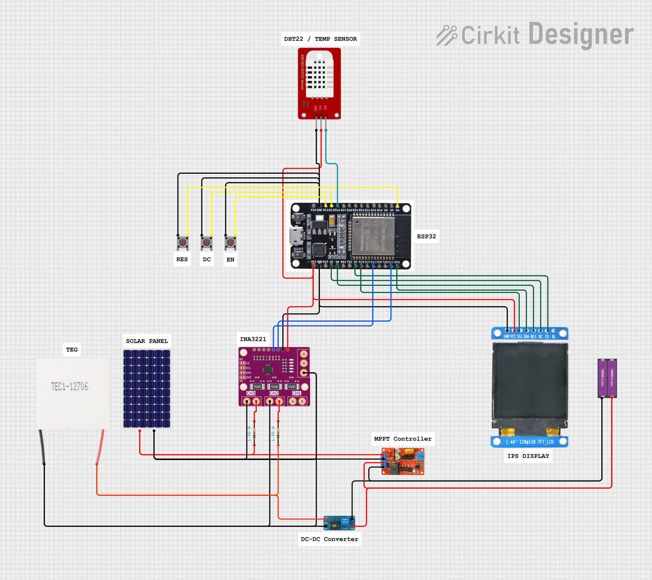
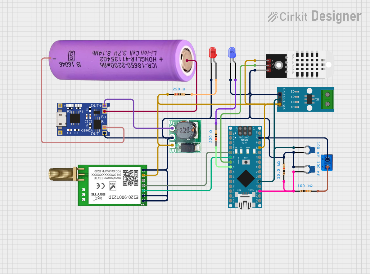
Explore Projects Built with HT-12E
Common Applications
- Wireless remote controls (e.g., garage doors, fans, and lighting systems)
- RF-based communication systems
- Home automation and security systems
- Robotics and IoT devices
Technical Specifications
Key Technical Details
| Parameter | Value |
|---|---|
| Operating Voltage | 2.4V to 12V |
| Operating Current | 0.1 mA (at 5V, no load) |
| Encoding Capability | 12 bits (8 address + 4 data bits) |
| Oscillator Frequency | 3 kHz to 1 MHz (external resistor) |
| Transmission Medium | RF or Infrared (IR) |
| Package Type | DIP-18 / SOP-18 |
Pin Configuration and Descriptions
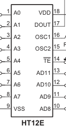
The HT-12E comes in an 18-pin package. Below is the pinout and description:
| Pin No. | Pin Name | Description |
|---|---|---|
| 1-8 | A0-A7 | Address pins (A0 to A7). Used to set the unique address of the encoder. |
| 9 | GND | Ground pin. Connect to the negative terminal of the power supply. |
| 10-13 | AD8-AD11 | Data pins (D0 to D3). Used to input the 4-bit data to be transmitted. |
| 14 | TE | Transmission Enable. Active LOW. Pull LOW to enable data transmission. |
| 15 | OSC1 | Oscillator input. Connect to an external resistor to set the frequency. |
| 16 | OSC2 | Oscillator output. Connect to the other end of the external resistor. |
| 17 | Dout | Encoded data output. Connect to the RF module or IR transmitter. |
| 18 | VCC | Positive power supply. Connect to the positive terminal of the power source. |
Usage Instructions
How to Use the HT-12E in a Circuit
- Power Supply: Connect the VCC pin to a power source (2.4V to 12V) and the GND pin to ground.
- Address Configuration: Set the address pins (A0 to A7) to a unique combination using pull-up or pull-down resistors. This ensures that only the paired decoder IC (e.g., HT-12D) with the same address will respond.
- Data Input: Connect the data pins (D0 to D3) to the switches or microcontroller outputs that will provide the 4-bit data to be transmitted.
- Oscillator Setup: Connect a resistor between the OSC1 and OSC2 pins to set the oscillator frequency. For most applications, a 1MΩ resistor is recommended.
- Transmission Enable: Pull the TE pin LOW to enable data transmission. When this pin is HIGH, the IC remains idle.
- Data Output: Connect the Dout pin to the data input of an RF transmitter module or IR LED driver circuit.
Example Circuit with RF Module
Below is an example of how to connect the HT-12E to an RF transmitter module:
- Connect the Dout pin of the HT-12E to the Data pin of the RF transmitter module.
- Ensure the RF receiver module is paired with an HT-12D decoder IC configured with the same address.
Arduino UNO Example Code
The HT-12E can also be used with an Arduino UNO to control the data pins programmatically. Below is an example code snippet:
// Example: Sending data using HT-12E with Arduino UNO
// Connect D0-D3 of HT-12E to Arduino pins 2-5
// Connect TE pin of HT-12E to Arduino pin 6

#define D0 2  // Data pin D0
#define D1 3  // Data pin D1
#define D2 4  // Data pin D2
#define D3 5  // Data pin D3
#define TE 6  // Transmission Enable pin

void setup() {
  // Set data pins as outputs
  pinMode(D0, OUTPUT);
  pinMode(D1, OUTPUT);
  pinMode(D2, OUTPUT);
  pinMode(D3, OUTPUT);

  // Set TE pin as output
  pinMode(TE, OUTPUT);

  // Initialize TE pin to HIGH (disable transmission)
  digitalWrite(TE, HIGH);
}

void loop() {
  // Example: Send binary data 1010 (D3-D0)
  digitalWrite(D3, HIGH);  // Set D3 to 1
  digitalWrite(D2, LOW);   // Set D2 to 0
  digitalWrite(D1, HIGH);  // Set D1 to 1
  digitalWrite(D0, LOW);   // Set D0 to 0

  // Enable transmission
  digitalWrite(TE, LOW);
  delay(100);  // Transmit for 100ms

  // Disable transmission
  digitalWrite(TE, HIGH);
  delay(1000);  // Wait for 1 second before next transmission
}
Important Considerations
- Ensure the address pins of the HT-12E and the paired decoder IC (e.g., HT-12D) are configured identically.
- Use a stable power supply to avoid transmission errors.
- Select an appropriate resistor for the oscillator to match the desired transmission speed.
Troubleshooting and FAQs
Common Issues and Solutions
No Data Transmission
- Cause: TE pin is not pulled LOW.
- Solution: Ensure the TE pin is connected to ground during transmission.
Receiver Not Responding
- Cause: Address mismatch between HT-12E and HT-12D.
- Solution: Verify that the address pins (A0 to A7) are configured identically on both ICs.
Unstable Transmission
- Cause: Incorrect oscillator resistor value.
- Solution: Use a 1MΩ resistor for most applications. Adjust if necessary.
High Power Consumption
- Cause: TE pin left LOW for extended periods.
- Solution: Pull the TE pin HIGH when not transmitting to reduce power consumption.
FAQs
Q1: Can the HT-12E be used with IR transmitters?
Yes, the HT-12E can be connected to an IR LED driver circuit for infrared communication.
Q2: What is the maximum range of the HT-12E?
The range depends on the RF module or IR transmitter used. Typical RF modules provide a range of 50-100 meters.
Q3: Can I use fewer than 8 address pins?
Yes, unused address pins can be left floating or tied to ground. However, ensure the same configuration is used on the paired decoder IC.
This concludes the documentation for the HT-12E.