How to Use BT139 600: Examples, Pinouts, and Specs
Introduction
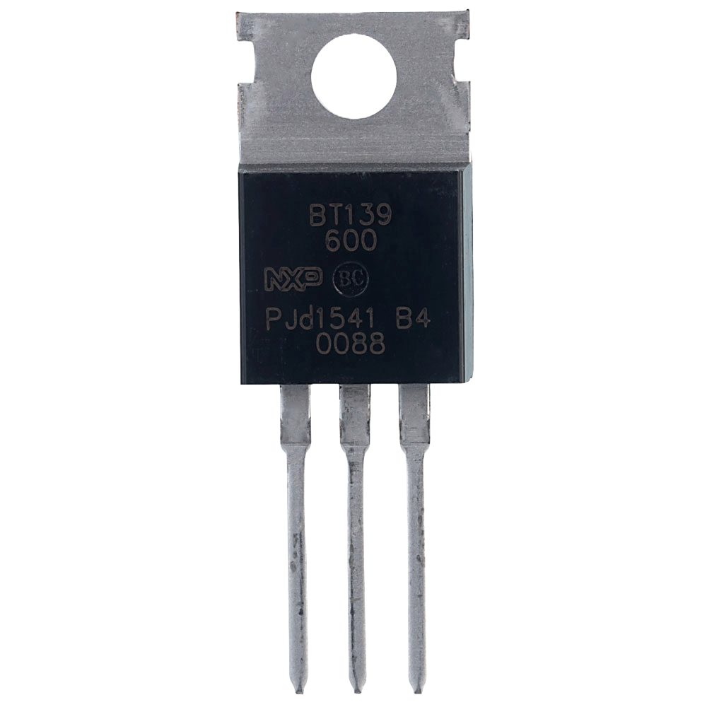
The BT139 600 is a widely used Triac, which is a type of semiconductor device that can conduct current in either direction when it is triggered. It is suitable for general-purpose AC switching applications, allowing for control of electrical power with high efficiency and fast switching. Common applications include motor control, dimming of lights, and heat control.
Explore Projects Built with BT139 600


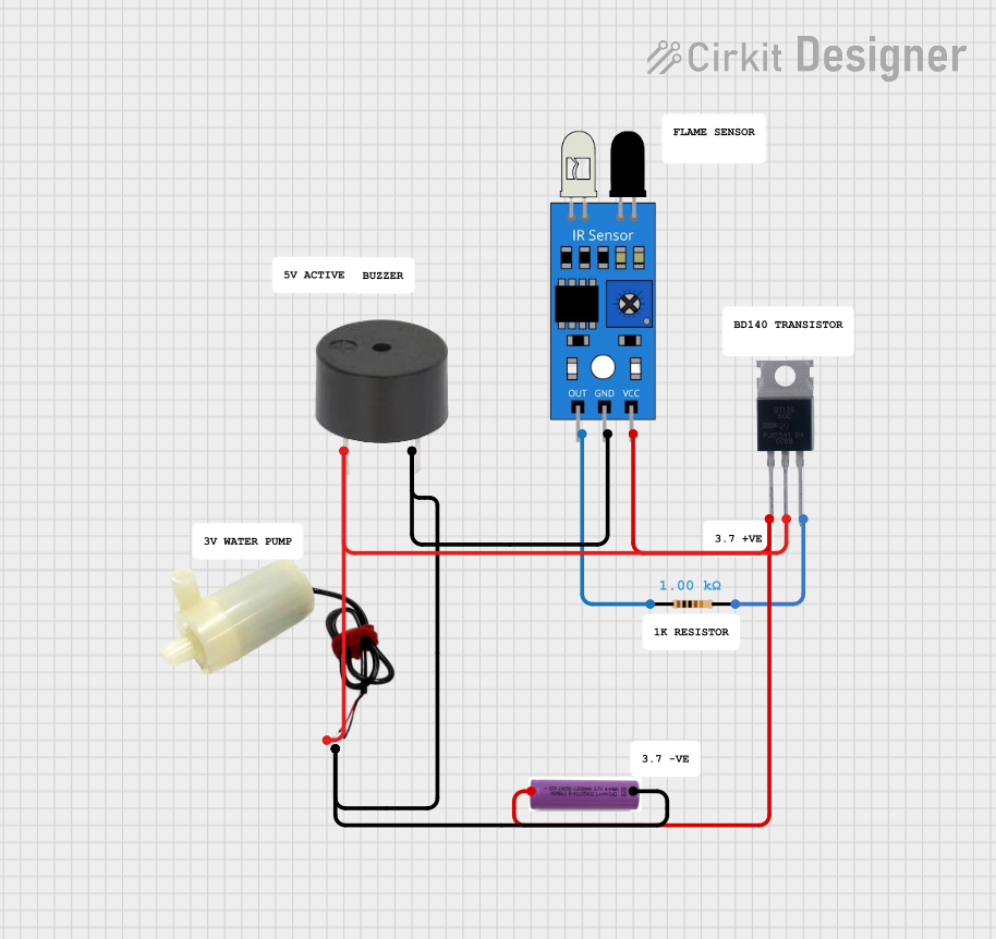
Explore Projects Built with BT139 600
Technical Specifications
Key Technical Details
- Maximum Repetitive Peak Off-State Voltage (Vdrm): 600V
- Maximum RMS On-State Current (It RMS): 16A
- Maximum Non-Repetitive Peak On-State Current (Itsm): 160A at 60Hz
- Gate Trigger Current (Igt): 5 to 35 mA
- Gate Trigger Voltage (Vgt): 1.5V
- Operating Junction Temperature Range (Tj): -40°C to +125°C
Pin Configuration and Descriptions
| Pin Number | Name | Description |
|---|---|---|
| 1 | MT1 | Main Terminal 1 - Connected to AC load |
| 2 | G | Gate - Controls the triggering of the Triac |
| 3 | MT2 | Main Terminal 2 - Connected to the other side of AC load |
Usage Instructions
How to Use the BT139 600 in a Circuit
Circuit Integration:
- Connect MT1 and MT2 across the AC load you wish to control.
- The Gate pin is used to trigger the Triac. A current applied to this pin will allow the Triac to conduct.
Gate Triggering:
- Use a resistor to limit the current to the gate from the control circuit.
- Ensure the gate trigger current (Igt) and voltage (Vgt) are within specified limits.
Heat Management:
- Due to power dissipation, the BT139 600 may require a heatsink to maintain safe operating temperatures.
Snubber Circuit:
- In inductive load applications, a snubber circuit may be necessary to prevent false triggering and protect the Triac from voltage spikes.
Best Practices
- Always verify that the load does not exceed the Triac's maximum ratings.
- Use an appropriate heatsink to prevent overheating.
- Ensure proper isolation between the high-voltage AC side and the low-voltage control side.
Troubleshooting and FAQs
Common Issues
Triac Not Triggering:
- Check if the gate current and voltage are within the specified range.
- Verify the connection of the gate resistor.
Overheating:
- Ensure the current through the Triac does not exceed the RMS current rating.
- Check if the heatsink is properly installed and of adequate size.
Unexpected Triggering:
- In inductive loads, ensure a snubber circuit is in place.
- Check for any noise in the circuit that could be falsely triggering the Triac.
FAQs
Q: Can the BT139 600 be used to control DC loads? A: No, the BT139 600 is designed for AC loads only.
Q: What is the function of a snubber circuit? A: A snubber circuit is used to suppress voltage spikes and prevent false triggering of the Triac.
Q: How do I choose a gate resistor? A: The gate resistor value should be chosen to limit the gate current within the specified Igt range, considering the control voltage source.
Example Code for Arduino UNO
Below is an example of how to control the BT139 600 using an Arduino UNO. This code will dim an AC light bulb using phase control.
// Define the pin connected to the Triac gate
const int triacGatePin = 2;

void setup() {
  pinMode(triacGatePin, OUTPUT);
  // Set up an interrupt on Timer1
  Timer1.initialize(100); // Set timer for 100 microseconds
  Timer1.attachInterrupt(dimCheck);
}

void loop() {
  // Adjust the brightness level from 0 to 100%
  for (int i = 0; i <= 100; i++) {
    setBrightness(i);
    delay(10);
  }
  for (int i = 100; i >= 0; i--) {
    setBrightness(i);
    delay(10);
  }
}

// Interrupt service routine to check for the dimming level
void dimCheck() {
  static int dimming = 128; // Dimming level (0-128) 0 = off, 128 = full on
  static int counter = 0;
  if (counter == 0) {
    digitalWrite(triacGatePin, HIGH); // Trigger the Triac gate
    delayMicroseconds(10); // Short pulse to trigger the Triac
    digitalWrite(triacGatePin, LOW);
  }
  counter++;
  if (counter >= dimming) {
    counter = 0;
  }
}

// Function to set the brightness level
void setBrightness(int brightness) {
  // Map brightness from 0-100% to 0-128
  int dimming = map(brightness, 0, 100, 128, 0);
  Timer1.setPeriod(100 * (128 - dimming)); // Adjust the timer period
}
Note: This code is for educational purposes and may require additional components and circuitry for proper operation, such as a zero-crossing detector for synchronized dimming. Always ensure safety when working with AC mains power.