How to Use Octocoupler: Examples, Pinouts, and Specs
Introduction
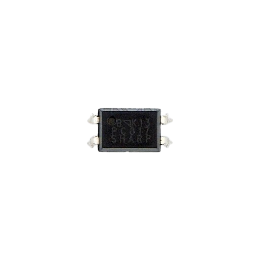
The PC817 is an optocoupler or photocoupler manufactured by Ktron. It is designed to transfer electrical signals between two isolated circuits by using light to transmit the signal. This component is widely used in applications requiring high-voltage isolation and noise immunity. Common applications include microprocessor system interfaces, signal isolation, and power supply regulation.
Explore Projects Built with Octocoupler

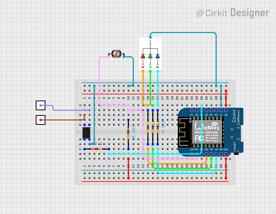

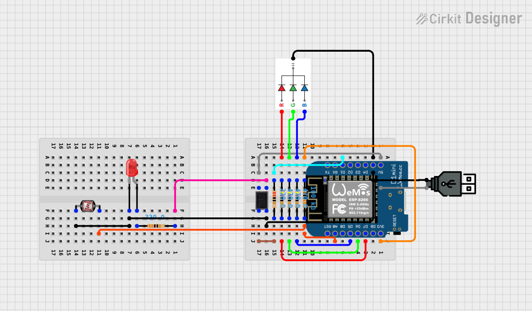
Explore Projects Built with Octocoupler
Technical Specifications
General Characteristics
- Package Type: 4-pin DIP
- Isolation Voltage: 5000Vrms (min)
- Current Transfer Ratio (CTR): 50% to 600% at IF=5mA, VCE=5V
- Input Forward Current (IF): 50mA (max)
- Output Collector-Emitter Voltage (VCEO): 35V (max)
- Output Emitter-Collector Voltage (VECO): 6V (max)
- Collector Current (IC): 50mA (max)
- Operating Temperature Range: -30°C to +100°C
Pin Configuration and Descriptions
| Pin Number | Name | Description |
|---|---|---|
| 1 | Anode (A) | Anode of the input infrared LED. |
| 2 | Cathode (K) | Cathode of the input infrared LED. |
| 3 | Emitter (E) | Emitter of the output phototransistor. |
| 4 | Collector (C) | Collector of the output phototransistor. |
Usage Instructions
Circuit Integration
To use the PC817 optocoupler in a circuit:
- Connect the input signal to the LED anode and cathode pins (1 and 2).
- The output phototransistor (pins 3 and 4) will then mirror the input signal with electrical isolation.
- A current-limiting resistor should be used in series with the LED to prevent excessive current.
Best Practices
- Ensure the input LED current is within the specified range to maintain proper operation.
- Avoid exceeding the maximum ratings of voltage and current to prevent damage.
- Use a pull-up resistor on the phototransistor output if interfacing with a microcontroller.
Example with Arduino UNO
// Example code to use PC817 with Arduino UNO
const int ledPin = 13; // LED connected to digital pin 13
const int inputPin = 2; // Optocoupler input connected to digital pin 2

void setup() {
  pinMode(ledPin, OUTPUT); // sets the digital pin as output
  pinMode(inputPin, INPUT); // sets the digital pin as input
}

void loop() {
  int sensorValue = digitalRead(inputPin); // read the input pin
  digitalWrite(ledPin, sensorValue); // sets the LED to the sensor value
}
Troubleshooting and FAQs
Common Issues
- LED not turning on: Check if the current-limiting resistor is correctly calculated and the input signal is within the specified range.
- No output signal: Ensure that the phototransistor's collector and emitter are correctly connected and that the pull-up resistor is in place if required.
FAQs
Q: Can the PC817 be used to isolate high voltages? A: Yes, the PC817 can provide electrical isolation up to 5000Vrms.
Q: What is the purpose of the current-limiting resistor? A: The resistor limits the current through the LED to prevent it from exceeding the maximum forward current rating.
Q: How do I choose the value of the pull-up resistor? A: The pull-up resistor value depends on the voltage level and the input impedance of the subsequent stage. A common value is 10kΩ for 5V systems.
Q: Can the PC817 be used with AC signals? A: The PC817 is designed for DC signal transmission. For AC signals, a different type of optocoupler with appropriate specifications should be used.
For further assistance or technical support, please contact Ktron customer service.