How to Use 1 Channel Relay 5V: Examples, Pinouts, and Specs
Introduction
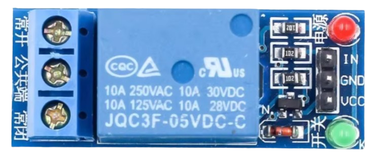
The 1 Channel Relay 5V module is an essential component in electronics, allowing a low-power 5V signal to control a higher power circuit. This relay module is commonly used for switching devices on and off, making it ideal for home automation, industrial control, and various DIY projects. It acts as an interface between microcontrollers (like Arduino) and high-power devices, ensuring safe and efficient control.
Explore Projects Built with 1 Channel Relay 5V


Explore Projects Built with 1 Channel Relay 5V
Technical Specifications
Key Technical Details
| Parameter | Value |
|---|---|
| Operating Voltage | 5V DC |
| Trigger Voltage | 0-5V DC |
| Current Rating | 10A @ 250V AC / 10A @ 30V DC |
| Relay Type | SPDT (Single Pole Double Throw) |
| Dimensions | 50mm x 26mm x 18.5mm |
| Weight | 20g |
Pin Configuration and Descriptions
| Pin Name | Description |
|---|---|
| VCC | Connects to the 5V power supply. |
| GND | Connects to the ground of the power supply. |
| IN | Control signal pin. Connects to the digital output pin of a microcontroller. |
| COM | Common terminal of the relay switch. |
| NO | Normally Open terminal. Connects to the load when the relay is activated. |
| NC | Normally Closed terminal. Connects to the load when the relay is not activated. |
Usage Instructions
How to Use the Component in a Circuit
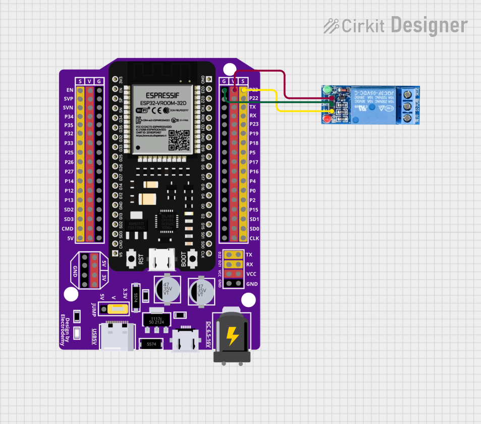
Power Connections:
- Connect the VCC pin to the 5V output of your power supply or microcontroller.
- Connect the GND pin to the ground of your power supply or microcontroller.
Control Signal:
- Connect the IN pin to a digital output pin of your microcontroller (e.g., Arduino).
Load Connections:
- Connect the device you want to control to the COM and NO/NC terminals of the relay.
- Use the NO terminal if you want the device to be off by default and turn on when the relay is activated.
- Use the NC terminal if you want the device to be on by default and turn off when the relay is activated.
Important Considerations and Best Practices
- Isolation: Ensure proper isolation between the low-power control circuit and the high-power load circuit to prevent damage and ensure safety.
- Flyback Diode: When controlling inductive loads (e.g., motors), use a flyback diode across the load to protect the relay from voltage spikes.
- Current Rating: Do not exceed the current rating of the relay to avoid overheating and potential failure.
- Secure Connections: Ensure all connections are secure to prevent loose wires and potential short circuits.
Example Code for Arduino UNO
/*
 * Example code to control a 1 Channel Relay 5V module using Arduino UNO.
 * This code turns the relay on for 2 seconds and then off for 2 seconds
 * in a loop.
 */

const int relayPin = 7; // Define the pin connected to the relay module

void setup() {
  pinMode(relayPin, OUTPUT); // Set the relay pin as an output
}

void loop() {
  digitalWrite(relayPin, HIGH); // Turn the relay on
  delay(2000); // Wait for 2 seconds
  digitalWrite(relayPin, LOW); // Turn the relay off
  delay(2000); // Wait for 2 seconds
}
Troubleshooting and FAQs
Common Issues Users Might Face
Relay Not Activating:
- Solution: Ensure the control signal voltage is within the specified range (0-5V). Check connections and power supply.
Relay Stuck in One State:
- Solution: Verify the control signal and ensure it is toggling correctly. Check for any short circuits or damaged components.
Overheating:
- Solution: Ensure the load current does not exceed the relay's rating. Use proper heat dissipation methods if necessary.
FAQs
Q1: Can I use the relay module with a 3.3V microcontroller?
- A1: Yes, but you may need a level shifter or transistor to ensure the control signal is within the relay's operating range.
Q2: Can I control AC devices with this relay module?
- A2: Yes, the relay can control AC devices up to 250V, but ensure proper isolation and safety precautions.
Q3: What is the difference between NO and NC terminals?
- A3: NO (Normally Open) means the circuit is open when the relay is not activated. NC (Normally Closed) means the circuit is closed when the relay is not activated.
By following this documentation, users can effectively integrate the 1 Channel Relay 5V module into their projects, ensuring safe and efficient control of high-power devices.