How to Use RPLIDAR A1 Adapter: Examples, Pinouts, and Specs
Introduction
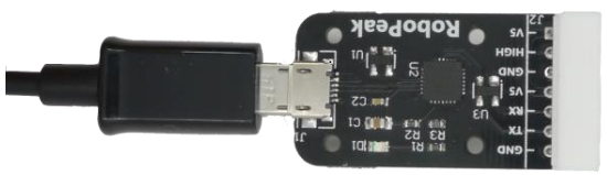
The RPLIDAR A1 Adapter, manufactured by Slamtec (Part ID: Adapter), is a specialized interface board designed to connect the RPLIDAR A1 laser scanner to a microcontroller or computer. It facilitates seamless communication and provides the necessary power supply for the RPLIDAR A1, making it an essential component for robotic and automation applications.
Explore Projects Built with RPLIDAR A1 Adapter

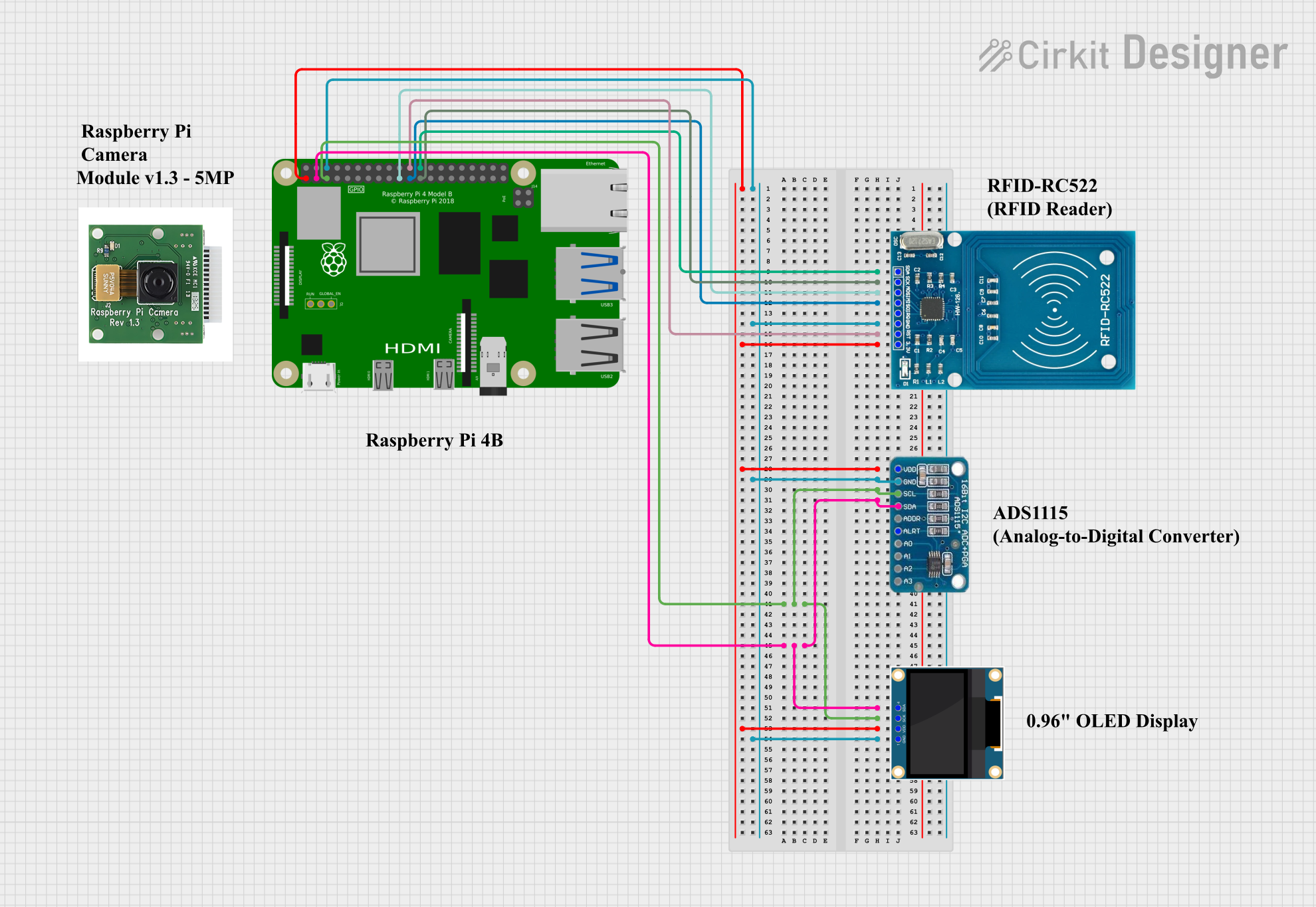

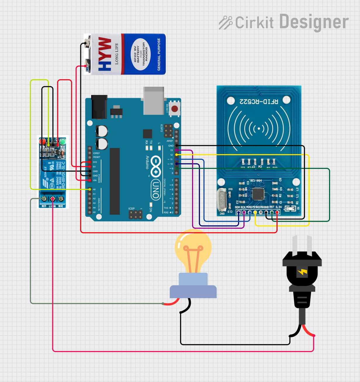
Explore Projects Built with RPLIDAR A1 Adapter
Common Applications and Use Cases
- Robotics and autonomous navigation systems
- Obstacle detection and avoidance
- 2D mapping and SLAM (Simultaneous Localization and Mapping)
- Industrial automation and monitoring
- Research and development in robotics and AI
Technical Specifications
The RPLIDAR A1 Adapter is designed to simplify the integration of the RPLIDAR A1 laser scanner into various systems. Below are the key technical details:
Key Technical Details
- Input Voltage: 5V DC (via USB or external power source)
- Communication Interface: UART (3.3V logic level)
- Power Output to RPLIDAR: 5V DC
- Dimensions: 50mm x 30mm x 10mm
- Weight: 10g
- Operating Temperature: 0°C to 40°C
- Connector Type: JST 4-pin connector for RPLIDAR A1
Pin Configuration and Descriptions
The RPLIDAR A1 Adapter features a 4-pin JST connector for connecting to the RPLIDAR A1 and a UART interface for communication with a microcontroller or computer. The pin configuration is as follows:
JST 4-Pin Connector (to RPLIDAR A1)
| Pin Number | Pin Name | Description |
|---|---|---|
| 1 | VCC | 5V power supply to RPLIDAR |
| 2 | GND | Ground connection |
| 3 | TX | UART transmit (to RPLIDAR RX) |
| 4 | RX | UART receive (from RPLIDAR TX) |
UART Interface (to Microcontroller/Computer)
| Pin Name | Description |
|---|---|
| TX | Transmit data from the adapter |
| RX | Receive data to the adapter |
| GND | Ground connection |
| VCC | Optional 5V input (if not using USB power) |
Usage Instructions
How to Use the RPLIDAR A1 Adapter in a Circuit
- Connect the RPLIDAR A1:
- Use the 4-pin JST cable to connect the RPLIDAR A1 to the adapter's JST connector.
- Power the Adapter:
- Connect the adapter to a 5V power source via USB or the VCC and GND pins on the UART interface.
- Establish Communication:
- Connect the TX and RX pins of the adapter to the RX and TX pins of your microcontroller or computer, respectively.
- Ensure the UART logic level is 3.3V to avoid damaging the adapter.
- Install Necessary Drivers:
- If using a computer, install the appropriate USB-to-UART drivers (e.g., CP2102 or CH340) to enable communication.
- Test the Connection:
- Use a serial terminal or software library to send and receive data from the RPLIDAR A1.
Important Considerations and Best Practices
- Power Supply: Ensure the adapter is powered with a stable 5V DC source. Avoid voltage fluctuations to prevent damage to the RPLIDAR A1.
- UART Logic Level: The adapter operates at 3.3V logic level. Use a level shifter if your microcontroller operates at 5V logic.
- Cable Length: Keep the cable between the adapter and RPLIDAR A1 as short as possible to minimize signal degradation.
- Driver Installation: Verify that the correct USB-to-UART driver is installed on your computer to avoid communication issues.
Example Code for Arduino UNO
Below is an example code snippet to interface the RPLIDAR A1 Adapter with an Arduino UNO:
#include <SoftwareSerial.h>

// Define RX and TX pins for SoftwareSerial
// Connect Arduino pin 10 to Adapter TX, and pin 11 to Adapter RX
SoftwareSerial lidarSerial(10, 11);

void setup() {
  Serial.begin(9600); // Initialize Serial Monitor at 9600 baud
  lidarSerial.begin(115200); // Initialize RPLIDAR communication at 115200 baud

  Serial.println("RPLIDAR A1 Adapter Test");
}

void loop() {
  // Check if data is available from the RPLIDAR
  if (lidarSerial.available()) {
    char data = lidarSerial.read(); // Read one byte of data
    Serial.print(data); // Print the data to the Serial Monitor
  }
}
Notes:
- Ensure the Arduino UNO is powered via USB or an external power source.
- The RPLIDAR A1 Adapter must be connected to the Arduino's 5V and GND pins for power.
Troubleshooting and FAQs
Common Issues and Solutions
No Data Received from RPLIDAR:
- Cause: Incorrect UART connection or baud rate mismatch.
- Solution: Verify the TX and RX connections. Ensure the baud rate is set to 115200.
RPLIDAR Does Not Power On:
- Cause: Insufficient power supply.
- Solution: Check the power source and ensure it provides a stable 5V DC.
Communication Errors:
- Cause: Incorrect UART logic level or driver issues.
- Solution: Use a level shifter if necessary. Reinstall the USB-to-UART driver.
Adapter Overheating:
- Cause: Prolonged operation in high-temperature environments.
- Solution: Operate the adapter within the specified temperature range (0°C to 40°C).
FAQs
Q1: Can the adapter be used with other RPLIDAR models?
A1: The adapter is specifically designed for the RPLIDAR A1. Compatibility with other models may vary.
Q2: What is the maximum cable length between the adapter and RPLIDAR A1?
A2: It is recommended to keep the cable length under 1 meter to ensure reliable communication.
Q3: Can I power the adapter directly from a microcontroller?
A3: Yes, as long as the microcontroller provides a stable 5V output and sufficient current.
Q4: Is the adapter compatible with Raspberry Pi?
A4: Yes, the adapter can be connected to a Raspberry Pi via the UART interface. Ensure proper wiring and configuration.
This concludes the documentation for the RPLIDAR A1 Adapter. For further assistance, refer to the official Slamtec documentation or support resources.