How to Use TL072: Examples, Pinouts, and Specs
Introduction
The TL072 is a low-noise JFET-input operational amplifier (op-amp) manufactured by Texas Instruments, with the part ID TL072CP. It is designed for high-speed, low-distortion applications, making it ideal for audio processing, signal amplification, and active filter designs. The TL072 features low input bias and offset currents, ensuring high accuracy and stability in sensitive analog circuits.
Explore Projects Built with TL072


Explore Projects Built with TL072
Common Applications
- Audio preamplifiers and mixers
- Active filters and equalizers
- Signal conditioning and processing
- Instrumentation amplifiers
- Data acquisition systems
Technical Specifications
The TL072 is a dual operational amplifier with the following key specifications:
| Parameter | Value |
|---|---|
| Supply Voltage Range | ±3V to ±18V (dual supply) |
| Input Offset Voltage | 3mV (typical) |
| Input Bias Current | 65pA (typical) |
| Slew Rate | 13V/µs (typical) |
| Gain Bandwidth Product | 3MHz |
| Input Impedance | 10⁹Ω |
| Output Voltage Swing | ±12V (with ±15V supply) |
| Total Harmonic Distortion | 0.003% (typical) |
| Operating Temperature Range | 0°C to 70°C |
| Package Type | PDIP, SOIC, TSSOP |
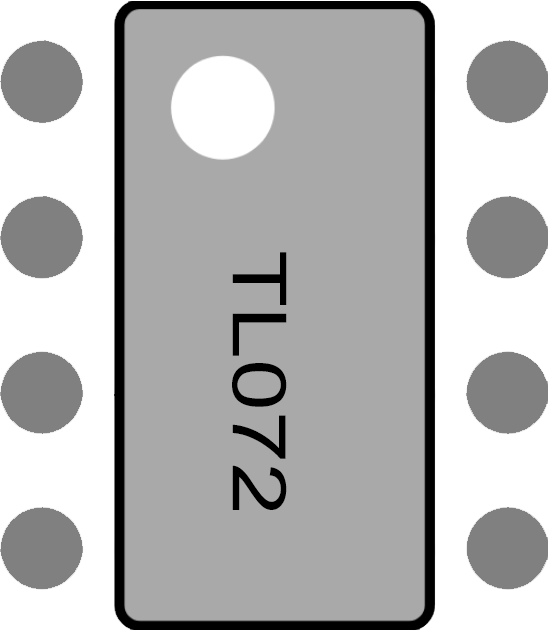
Pin Configuration
The TL072 is available in an 8-pin package. Below is the pinout and description:
| Pin Number | Pin Name | Description |
|---|---|---|
| 1 | OUT A | Output of Op-Amp A |
| 2 | IN- A | Inverting Input of Op-Amp A |
| 3 | IN+ A | Non-Inverting Input of Op-Amp A |
| 4 | V- (GND) | Negative Power Supply (or Ground) |
| 5 | IN+ B | Non-Inverting Input of Op-Amp B |
| 6 | IN- B | Inverting Input of Op-Amp B |
| 7 | OUT B | Output of Op-Amp B |
| 8 | V+ | Positive Power Supply |
Usage Instructions
Using the TL072 in a Circuit
- Power Supply: Connect the TL072 to a dual power supply (e.g., ±15V) or a single supply (e.g., 0V and +12V). Ensure the supply voltage does not exceed the maximum rating of ±18V.
- Input Connections: Use the IN+ and IN- pins for the non-inverting and inverting inputs, respectively. For single-ended signals, connect the unused input to ground or a reference voltage.
- Output: The output pin (OUT) provides the amplified signal. Ensure the load impedance is high enough to avoid excessive current draw.
- Bypass Capacitors: Place decoupling capacitors (e.g., 0.1µF ceramic and 10µF electrolytic) close to the power supply pins to reduce noise and improve stability.
- Feedback Network: Use resistors and capacitors in the feedback loop to set the gain and frequency response of the amplifier.
Example Circuit: Non-Inverting Amplifier
Below is a simple non-inverting amplifier circuit using the TL072:
        +V (e.g., +15V)
         |
         |
        [R2]  <-- Feedback Resistor
         |       (e.g., 10kΩ)
         +-----> OUT (Pin 1)
         |
        [R1]  <-- Input Resistor
         |       (e.g., 1kΩ)
         |
Input --> IN+ (Pin 3)
         |
        GND
The gain of the circuit is determined by the formula:
Gain = 1 + (R2 / R1)
Arduino Example: Signal Amplification
The TL072 can be used with an Arduino UNO to amplify an analog signal before feeding it into the Arduino's ADC. Below is an example:
// Example: Amplifying a signal with TL072 and reading it with Arduino UNO

const int analogPin = A0; // Analog pin to read the amplified signal
int signalValue = 0;      // Variable to store the ADC value

void setup() {
  Serial.begin(9600); // Initialize serial communication
}

void loop() {
  signalValue = analogRead(analogPin); // Read the amplified signal
  Serial.print("Amplified Signal Value: ");
  Serial.println(signalValue); // Print the ADC value to the serial monitor
  delay(100); // Delay for stability
}
Note: Ensure the amplified signal does not exceed the Arduino's ADC input range (0-5V).
Best Practices
- Use precision resistors in the feedback network for accurate gain settings.
- Avoid driving capacitive loads directly; use a small resistor (e.g., 50Ω) in series with the output if necessary.
- Keep input and output traces short to minimize noise and interference.
Troubleshooting and FAQs
Common Issues
No Output Signal:
- Check the power supply connections and ensure the voltage is within the specified range.
- Verify that the input signal is connected to the correct pins (IN+ or IN-).
Distorted Output:
- Ensure the load impedance is not too low, as this can cause excessive current draw.
- Check for proper decoupling capacitors on the power supply lines.
High Noise Levels:
- Use shielded cables for input signals and keep the circuit layout compact.
- Add bypass capacitors close to the power supply pins.
Overheating:
- Verify that the supply voltage does not exceed ±18V.
- Ensure the output is not shorted to ground or the power supply.
FAQs
Q1: Can the TL072 operate with a single power supply?
Yes, the TL072 can operate with a single supply (e.g., 0V and +12V). However, the input signal and output swing must remain within the supply voltage range.
Q2: What is the maximum gain I can achieve with the TL072?
The maximum gain depends on the feedback network and the bandwidth of the op-amp. For high gains, the bandwidth will decrease due to the gain-bandwidth product (3MHz).
Q3: Can I use the TL072 for audio applications?
Yes, the TL072 is well-suited for audio applications due to its low noise, low distortion, and high input impedance.
Q4: How do I protect the TL072 from damage?
Use proper decoupling capacitors, avoid exceeding the supply voltage range, and ensure the output is not shorted to ground or the power supply.
By following these guidelines, the TL072 can be effectively used in a wide range of analog circuit designs.