Cirkit Designer Logo
Cirkit Designer
Your all-in-one circuit design IDE
Home / 
Component Documentation

How to Use Hall Effect Sensor: Examples, Pinouts, and Specs

Image of Hall Effect Sensor
Cirkit Designer LogoDesign with Hall Effect Sensor in Cirkit Designer

Introduction

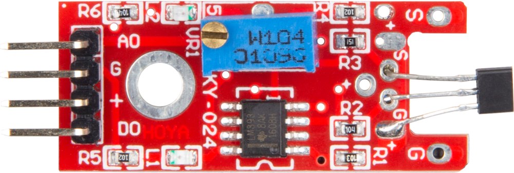
The JOY-IT KY-024 Hall Effect Sensor is a versatile electronic component designed to detect the presence and strength of a magnetic field. It operates based on the Hall effect principle, which generates a voltage proportional to the magnetic field when current flows through a conductor. This sensor is widely used in applications requiring magnetic field detection, such as proximity sensing, speed measurement, and current sensing.

Explore Projects Built with Hall Effect Sensor

Use Cirkit Designer to design, explore, and prototype these projects online. Some projects support real-time simulation. Click "Open Project" to start designing instantly!
Magnetic Field-Activated Solenoid Array with Arduino Control
Image of Railgun: A project utilizing Hall Effect Sensor in a practical application
This circuit is designed to use Hall effect sensors for magnetic field detection, interfaced with an Arduino UNO microcontroller to control an array of solenoids through MOSFETs. It includes user interface elements such as a tactile switch and LED, and features flyback diodes for solenoid protection.
Cirkit Designer LogoOpen Project in Cirkit Designer
Arduino Nano 33 BLE Magnetic Levitation System with Hall Sensor Feedback and Status LED Indicator
Image of LEVITRON: A project utilizing Hall Effect Sensor in a practical application
This circuit is designed for a magnetic levitation system that uses a Hall sensor to detect magnetic field strength and a TIP120 transistor to control the current through a levitating coil. An Arduino Nano 33 BLE microcontroller reads the sensor and adjusts the coil current via PWM to maintain levitation, while an LED indicates the system's status. The circuit includes power management with 5V DC sources and protective components like diodes and resistors for current control and indication.
Cirkit Designer LogoOpen Project in Cirkit Designer
Arduino Nano ESP32 Hall Sensor Interface with LCD Display
Image of hall effect + speedometer: A project utilizing Hall Effect Sensor in a practical application
This circuit includes a Hall sensor connected to an Arduino Nano ESP32 microcontroller, which is likely used to detect magnetic fields and send the data to the microcontroller on pin D12. The Arduino is also interfaced with an LCD display, with connections for power, ground, control (RS, E), and data (DB4-DB7) to display information. The absence of code suggests that the microcontroller's behavior is not defined in this context, but it is set up to read the Hall sensor and output to the LCD.
Cirkit Designer LogoOpen Project in Cirkit Designer
Arduino Nano-Based Propeller LED Pendulum Clock with Hall Sensor and Battery Power
Image of circuit diagram: A project utilizing Hall Effect Sensor in a practical application
This circuit features an Arduino Nano microcontroller interfaced with a Hall effect sensor and multiple LEDs of different colors, each paired with a resistor. The Arduino is programmed to act as a propeller LED pendulum clock, where the Hall sensor likely detects magnetic fields to synchronize the movement of the propeller, and the LEDs display time-related information. The code controls the lighting pattern of the LEDs to represent hours, minutes, and seconds, and allows for time adjustments via serial commands.
Cirkit Designer LogoOpen Project in Cirkit Designer

Explore Projects Built with Hall Effect Sensor

Use Cirkit Designer to design, explore, and prototype these projects online. Some projects support real-time simulation. Click "Open Project" to start designing instantly!
Image of Railgun: A project utilizing Hall Effect Sensor in a practical application
Magnetic Field-Activated Solenoid Array with Arduino Control
This circuit is designed to use Hall effect sensors for magnetic field detection, interfaced with an Arduino UNO microcontroller to control an array of solenoids through MOSFETs. It includes user interface elements such as a tactile switch and LED, and features flyback diodes for solenoid protection.
Cirkit Designer LogoOpen Project in Cirkit Designer
Image of LEVITRON: A project utilizing Hall Effect Sensor in a practical application
Arduino Nano 33 BLE Magnetic Levitation System with Hall Sensor Feedback and Status LED Indicator
This circuit is designed for a magnetic levitation system that uses a Hall sensor to detect magnetic field strength and a TIP120 transistor to control the current through a levitating coil. An Arduino Nano 33 BLE microcontroller reads the sensor and adjusts the coil current via PWM to maintain levitation, while an LED indicates the system's status. The circuit includes power management with 5V DC sources and protective components like diodes and resistors for current control and indication.
Cirkit Designer LogoOpen Project in Cirkit Designer
Image of hall effect + speedometer: A project utilizing Hall Effect Sensor in a practical application
Arduino Nano ESP32 Hall Sensor Interface with LCD Display
This circuit includes a Hall sensor connected to an Arduino Nano ESP32 microcontroller, which is likely used to detect magnetic fields and send the data to the microcontroller on pin D12. The Arduino is also interfaced with an LCD display, with connections for power, ground, control (RS, E), and data (DB4-DB7) to display information. The absence of code suggests that the microcontroller's behavior is not defined in this context, but it is set up to read the Hall sensor and output to the LCD.
Cirkit Designer LogoOpen Project in Cirkit Designer
Image of circuit diagram: A project utilizing Hall Effect Sensor in a practical application
Arduino Nano-Based Propeller LED Pendulum Clock with Hall Sensor and Battery Power
This circuit features an Arduino Nano microcontroller interfaced with a Hall effect sensor and multiple LEDs of different colors, each paired with a resistor. The Arduino is programmed to act as a propeller LED pendulum clock, where the Hall sensor likely detects magnetic fields to synchronize the movement of the propeller, and the LEDs display time-related information. The code controls the lighting pattern of the LEDs to represent hours, minutes, and seconds, and allows for time adjustments via serial commands.
Cirkit Designer LogoOpen Project in Cirkit Designer

Common Applications and Use Cases

  • Proximity sensing: Detecting the presence of magnetic objects.
  • Speed measurement: Monitoring the rotational speed of motors or wheels.
  • Current sensing: Measuring current in circuits using magnetic fields.
  • Position sensing: Determining the position of moving parts in machinery.
  • Magnetic field strength measurement: Quantifying the intensity of magnetic fields.

Technical Specifications

The following table outlines the key technical details of the JOY-IT KY-024 Hall Effect Sensor:

Parameter Value
Operating Voltage 3.3V to 5V
Output Type Analog and Digital
Sensitivity Adjustment Potentiometer (onboard)
Dimensions 32mm x 14mm x 7mm
Operating Temperature -40°C to +85°C
Magnetic Field Detection Bipolar (North and South poles)

Pin Configuration and Descriptions

The KY-024 module has three pins for interfacing:

Pin Name Description
1 VCC Power supply pin (3.3V to 5V). Connect to the positive terminal of the power source.
2 GND Ground pin. Connect to the negative terminal of the power source.
3 OUT Output pin. Provides both analog and digital signals based on the magnetic field.

Usage Instructions

How to Use the KY-024 in a Circuit

  1. Power the Sensor: Connect the VCC pin to a 3.3V or 5V power source and the GND pin to ground.
  2. Connect the Output:
    • For digital output, connect the OUT pin to a digital input pin of your microcontroller.
    • For analog output, connect the OUT pin to an analog input pin of your microcontroller.
  3. Adjust Sensitivity: Use the onboard potentiometer to adjust the sensitivity of the sensor to the magnetic field.
  4. Place the Sensor: Position the sensor near the magnetic field source. Ensure the magnetic field is perpendicular to the sensor for optimal detection.

Important Considerations and Best Practices

  • Power Supply: Ensure the sensor operates within the specified voltage range (3.3V to 5V) to avoid damage.
  • Magnetic Field Orientation: For accurate detection, align the sensor perpendicular to the magnetic field.
  • Noise Reduction: Use decoupling capacitors near the power supply pins to reduce noise in the circuit.
  • Avoid Overheating: Operate the sensor within the specified temperature range (-40°C to +85°C).

Example: Connecting to an Arduino UNO

Below is an example of how to use the KY-024 Hall Effect Sensor with an Arduino UNO to read both digital and analog outputs.

// KY-024 Hall Effect Sensor Example with Arduino UNO
// Reads both digital and analog outputs from the sensor

// Define pin connections
const int digitalPin = 2;  // Digital output pin from KY-024
const int analogPin = A0;  // Analog output pin from KY-024

void setup() {
  pinMode(digitalPin, INPUT);  // Set digital pin as input
  Serial.begin(9600);         // Initialize serial communication
}

void loop() {
  // Read digital output
  int digitalValue = digitalRead(digitalPin);
  
  // Read analog output
  int analogValue = analogRead(analogPin);
  
  // Print values to the Serial Monitor
  Serial.print("Digital Output: ");
  Serial.print(digitalValue);
  Serial.print(" | Analog Output: ");
  Serial.println(analogValue);
  
  delay(500);  // Wait for 500ms before the next reading
}

Troubleshooting and FAQs

Common Issues and Solutions

  1. No Output from the Sensor:

    • Cause: Incorrect wiring or insufficient power supply.
    • Solution: Double-check the connections and ensure the power supply is within the specified range (3.3V to 5V).
  2. Inconsistent Readings:

    • Cause: Noise in the circuit or improper placement of the sensor.
    • Solution: Add decoupling capacitors near the power pins and ensure the sensor is properly aligned with the magnetic field.
  3. Sensor Not Detecting Magnetic Fields:

    • Cause: Sensitivity not adjusted correctly.
    • Solution: Use the onboard potentiometer to fine-tune the sensitivity.
  4. Overheating of the Sensor:

    • Cause: Operating outside the specified temperature range.
    • Solution: Ensure the sensor is used within the -40°C to +85°C range.

FAQs

Q1: Can the KY-024 detect both North and South poles of a magnet?
A1: Yes, the KY-024 is a bipolar sensor and can detect both North and South poles of a magnetic field.

Q2: What is the difference between the analog and digital outputs?
A2: The analog output provides a continuous voltage proportional to the magnetic field strength, while the digital output is a binary signal (HIGH or LOW) that indicates whether the magnetic field exceeds a certain threshold.

Q3: Can I use the KY-024 with a 3.3V microcontroller?
A3: Yes, the KY-024 operates within a voltage range of 3.3V to 5V, making it compatible with 3.3V microcontrollers.

Q4: How do I adjust the sensitivity of the sensor?
A4: Use the onboard potentiometer to increase or decrease the sensitivity to the magnetic field.

Q5: Is the KY-024 suitable for outdoor use?
A5: The KY-024 is not weatherproof. If used outdoors, ensure it is enclosed in a protective casing to prevent damage from moisture or dust.