
How to Use ID-12_20: Examples, Pinouts, and Specs
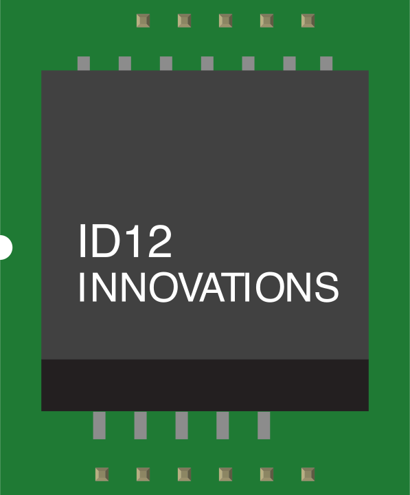
 Design with ID-12_20 in Cirkit Designer
Introduction
The ID-12_20, manufactured by ID Innovations, is an infrared receiver module designed for detecting and decoding infrared (IR) signals. It is widely used in remote control applications, such as consumer electronics, home automation systems, and robotics. The module is capable of receiving signals from a variety of IR remote controls, making it a versatile and reliable choice for IR-based communication.
Explore Projects Built with ID-12_20
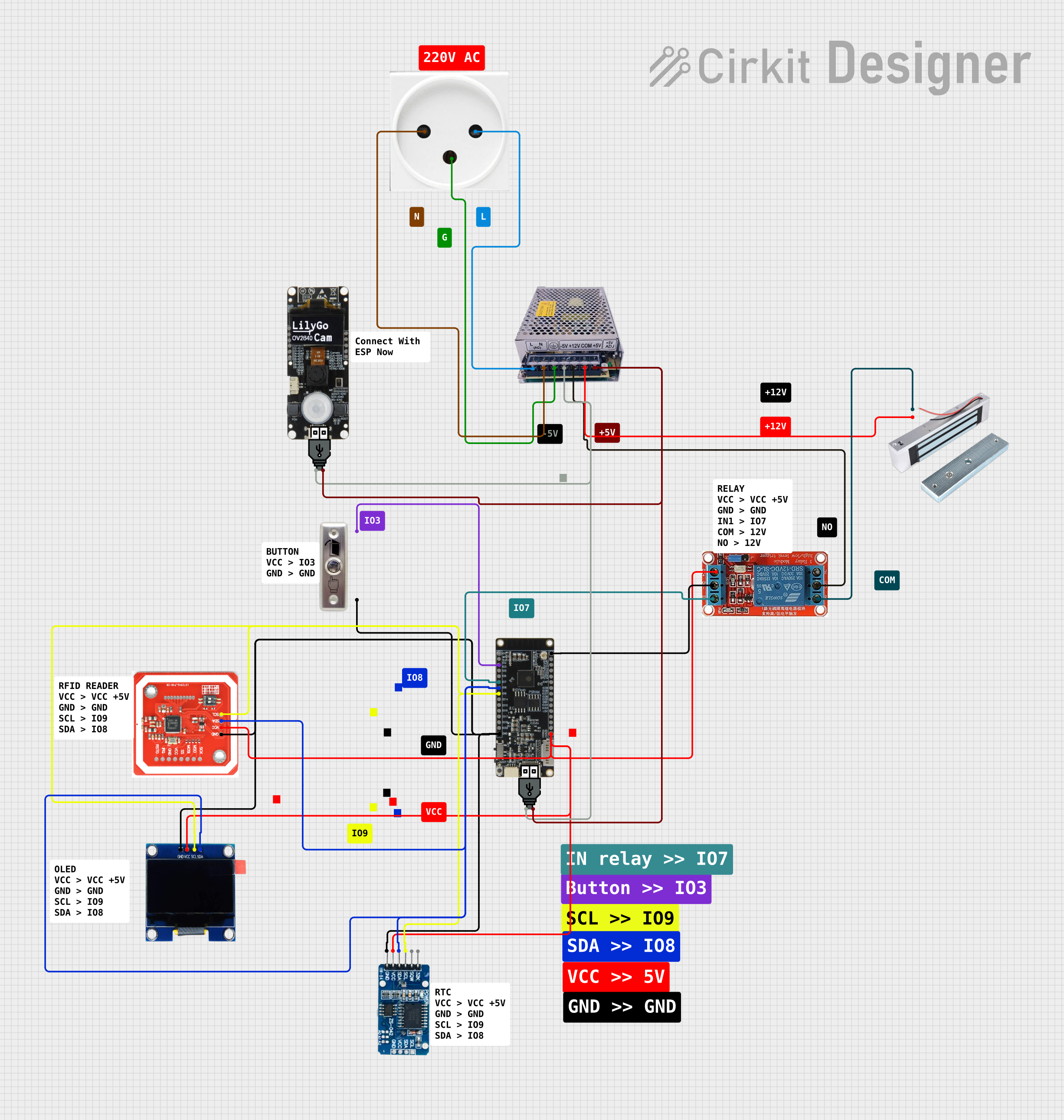 Open Project in Cirkit Designer
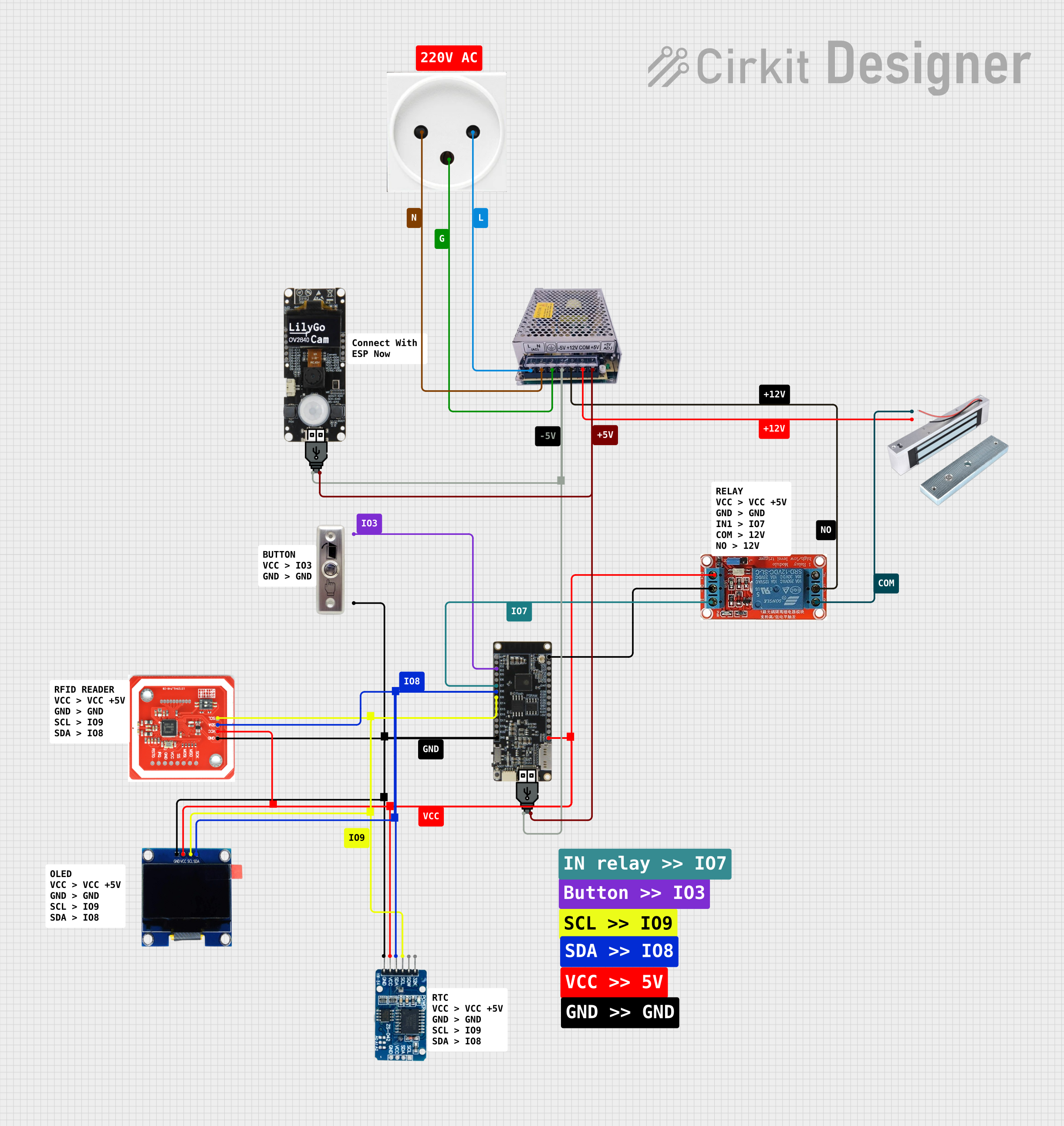 Open Project in Cirkit Designer
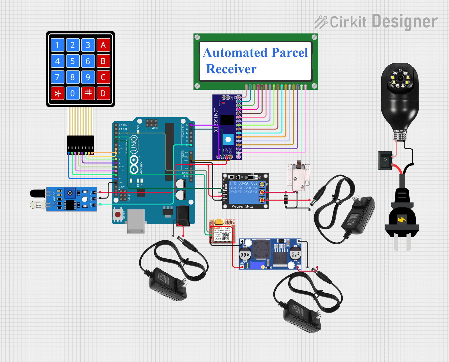 Open Project in Cirkit Designer
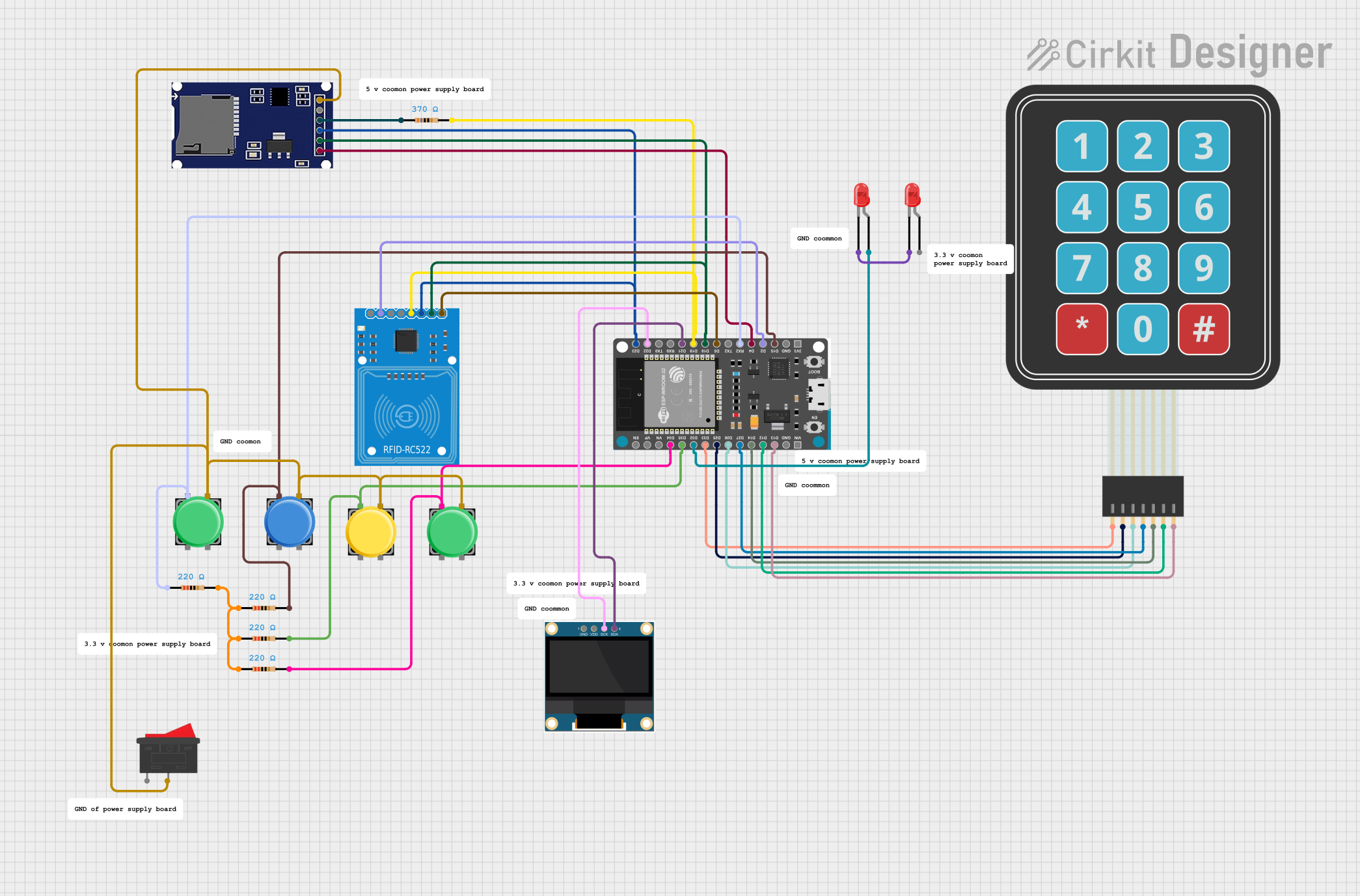 Open Project in Cirkit Designer
Explore Projects Built with ID-12_20
Open Project in Cirkit DesignerOpen Project in Cirkit DesignerOpen Project in Cirkit DesignerOpen Project in Cirkit DesignerCommon Applications
- Remote control signal reception for TVs, audio systems, and other appliances
- Home automation systems
- Robotics and embedded systems
- IR-based wireless communication
- Prototyping and educational projects
Technical Specifications
The ID-12_20 module is available in two variants: ID-12 and ID-20. Both variants share similar functionality but differ in their physical dimensions and range. Below are the key technical specifications:
| Parameter | ID-12 | ID-20 |
|---|---|---|
| Operating Voltage | 4.5V to 5.5V | 4.5V to 5.5V |
| Current Consumption | 5 mA (typical) | 5 mA (typical) |
| Carrier Frequency | 38 kHz | 38 kHz |
| Reception Range | Up to 10 meters | Up to 15 meters |
| Output Format | Digital (active low) | Digital (active low) |
| Operating Temperature | -20°C to +85°C | -20°C to +85°C |
| Dimensions | 23mm x 23mm x 7mm | 25mm x 25mm x 7mm |
Pin Configuration and Descriptions
The ID-12_20 module has a simple 3-pin interface for easy integration into circuits. Below is the pin configuration:
| Pin | Name | Description |
|---|---|---|
| 1 | VCC | Power supply input (4.5V to 5.5V) |
| 2 | GND | Ground connection |
| 3 | OUT | Digital output (active low when IR signal detected) |
Usage Instructions
How to Use the Component in a Circuit
- Power Supply: Connect the VCC pin to a 5V power source and the GND pin to the ground of your circuit.
- Signal Output: Connect the OUT pin to a microcontroller or other digital input device to read the IR signal.
- IR Signal Reception: Ensure the module has a clear line of sight to the IR transmitter for optimal performance. Avoid obstructions or interference from other IR sources.
Circuit Example
Below is a simple example of connecting the ID-12_20 to an Arduino UNO:
Circuit Connections
- Connect the VCC pin of the ID-12_20 to the 5V pin on the Arduino.
- Connect the GND pin of the ID-12_20 to the GND pin on the Arduino.
- Connect the OUT pin of the ID-12_20 to digital pin 2 on the Arduino.
Arduino Code Example
// Include the IRremote library for decoding IR signals
#include <IRremote.h>

// Define the pin connected to the OUT pin of the ID-12_20
const int IR_RECEIVER_PIN = 2;

// Create an IR receiver object
IRrecv irrecv(IR_RECEIVER_PIN);
decode_results results;

void setup() {
  Serial.begin(9600); // Initialize serial communication
  irrecv.enableIRIn(); // Start the IR receiver
  Serial.println("IR Receiver Ready");
}

void loop() {
  // Check if an IR signal is received
  if (irrecv.decode(&results)) {
    Serial.print("IR Code Received: ");
    Serial.println(results.value, HEX); // Print the received IR code in HEX
    irrecv.resume(); // Prepare to receive the next signal
  }
}
Important Considerations and Best Practices
- Power Supply: Ensure a stable 5V power supply to avoid erratic behavior.
- Interference: Minimize interference from other IR sources, such as sunlight or fluorescent lights.
- Placement: Position the module to face the IR transmitter directly for optimal signal reception.
- Decoding: Use an appropriate library (e.g., IRremote for Arduino) to decode the received IR signals.
Troubleshooting and FAQs
Common Issues and Solutions
No Signal Detected:
- Ensure the IR transmitter is functioning and emitting signals.
- Verify the module's connections (VCC, GND, and OUT).
- Check for obstructions or interference in the IR signal path.
Erratic Behavior:
- Confirm that the power supply is stable and within the specified voltage range.
- Avoid placing the module near strong light sources or reflective surfaces.
Short Reception Range:
- Ensure the IR transmitter is within the specified range of the module.
- Clean the module's IR sensor to remove dust or smudges.
FAQs
Q: Can the ID-12_20 receive signals from any IR remote control?
A: Yes, the module is compatible with most IR remote controls operating at a 38 kHz carrier frequency.
Q: What is the difference between the ID-12 and ID-20?
A: The primary difference is the reception range and physical dimensions. The ID-20 offers a longer range (up to 15 meters) compared to the ID-12 (up to 10 meters).
Q: Can I use the ID-12_20 with a 3.3V microcontroller?
A: The module requires a 4.5V to 5.5V power supply. However, the output signal can be interfaced with a 3.3V microcontroller using a level shifter or voltage divider.
Q: How do I decode the received IR signals?
A: Use an IR decoding library, such as IRremote for Arduino, to interpret the received signals and extract the data.
By following this documentation, you can effectively integrate the ID-12_20 into your projects and troubleshoot any issues that may arise.