How to Use SN65HVD230 CAN: Examples, Pinouts, and Specs
Introduction
The SN65HVD230 CAN is a high-speed CAN (Controller Area Network) transceiver designed to facilitate communication between a CAN controller and the physical CAN bus. Manufactured by Texas Instruments, this device supports data rates of up to 1 Mbps, making it ideal for high-speed and reliable communication in automotive, industrial, and embedded systems.
The transceiver is engineered for robust performance, offering low power consumption, high noise immunity, and compatibility with 3.3V systems. Its compact design and advanced features make it a popular choice for applications requiring efficient and reliable data transmission over a CAN network.
Explore Projects Built with SN65HVD230 CAN


Explore Projects Built with SN65HVD230 CAN
Common Applications
- Automotive systems (e.g., engine control units, body electronics)
- Industrial automation and control
- Medical equipment
- Building automation
- Embedded systems requiring CAN communication
Technical Specifications
Key Technical Details
| Parameter | Value |
|---|---|
| Supply Voltage (Vcc) | 3.3V |
| Data Rate | Up to 1 Mbps |
| Bus Voltage Range | -7V to +12V |
| Operating Temperature | -40°C to +125°C |
| Standby Current | < 370 µA |
| Differential Input Voltage | ±12V |
| ESD Protection | ±16 kV (Human Body Model) |
| Package Type | SOIC-8 |
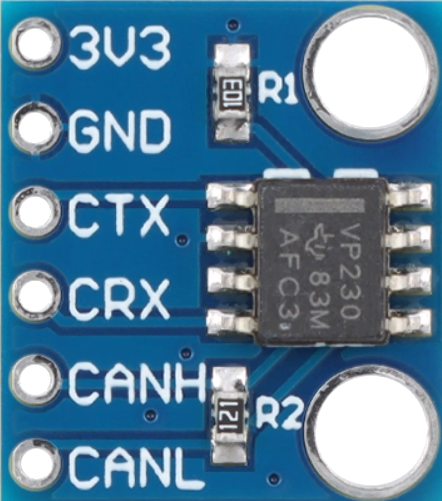
Pin Configuration and Descriptions
The SN65HVD230 is available in an 8-pin SOIC package. Below is the pinout and description:
| Pin No. | Pin Name | Description |
|---|---|---|
| 1 | D | Driver Input: Data input from the CAN controller |
| 2 | GND | Ground: Connect to system ground |
| 3 | Vcc | Supply Voltage: Connect to a 3.3V power supply |
| 4 | R | Receiver Output: Data output to the CAN controller |
| 5 | CANL | CAN Low: Connect to the CAN bus low line |
| 6 | CANH | CAN High: Connect to the CAN bus high line |
| 7 | Rs | Slope Control: Adjusts the slew rate of the driver (connect resistor to GND) |
| 8 | NC | No Connection: Leave unconnected |
Usage Instructions
How to Use the SN65HVD230 in a Circuit
- Power Supply: Connect the Vcc pin to a 3.3V power source and the GND pin to the system ground.
- CAN Bus Connection: Connect the CANH and CANL pins to the respective high and low lines of the CAN bus.
- Data Interface:
- Connect the
Dpin to the TX output of the CAN controller. - Connect the
Rpin to the RX input of the CAN controller.
- Connect the
- Slew Rate Control: Use the
Rspin to control the slew rate of the driver. For high-speed operation, connectRsdirectly to ground. For reduced EMI, connect a resistor betweenRsand ground. - Termination Resistor: Add a 120-ohm termination resistor between CANH and CANL at each end of the CAN bus to ensure proper signal integrity.
Important Considerations and Best Practices
- Ensure the supply voltage does not exceed 3.3V to avoid damaging the device.
- Use proper decoupling capacitors (e.g., 0.1 µF) near the Vcc pin to stabilize the power supply.
- Place the transceiver as close as possible to the CAN bus to minimize signal degradation.
- Avoid long stubs on the CAN bus to reduce reflections and maintain signal quality.
- For applications requiring low power consumption, use the standby mode by configuring the
Rspin appropriately.
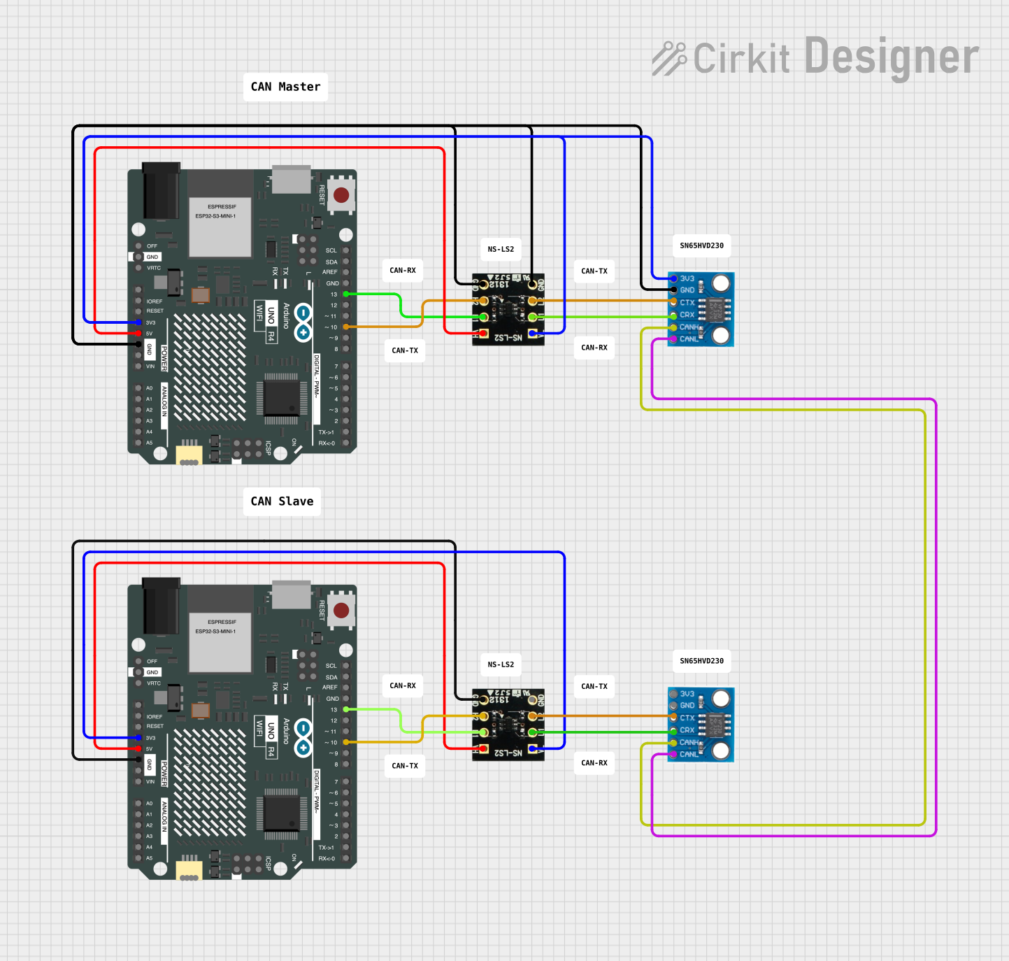
Example: Connecting SN65HVD230 to an Arduino UNO
The SN65HVD230 can be used with an Arduino UNO to enable CAN communication. Below is an example of how to connect the transceiver to the Arduino and a sample code snippet:
Wiring Diagram
| SN65HVD230 Pin | Arduino Pin |
|---|---|
| D | TX (Pin 1) |
| R | RX (Pin 0) |
| Vcc | 3.3V |
| GND | GND |
| CANH | CAN Bus High |
| CANL | CAN Bus Low |
Sample Code
#include <SPI.h>
#include <mcp_can.h>

// Define the CAN bus CS pin
#define CAN_CS 10

// Initialize the CAN bus object
MCP_CAN CAN(CAN_CS);

void setup() {
  Serial.begin(115200); // Initialize serial communication for debugging
  while (!Serial);

  // Initialize the CAN bus at 500 kbps
  if (CAN.begin(MCP_ANY, 500000, MCP_8MHZ) == CAN_OK) {
    Serial.println("CAN bus initialized successfully!");
  } else {
    Serial.println("Error initializing CAN bus.");
    while (1);
  }

  CAN.setMode(MCP_NORMAL); // Set CAN bus to normal mode
  Serial.println("CAN bus set to normal mode.");
}

void loop() {
  // Send a test message
  byte data[8] = {0x01, 0x02, 0x03, 0x04, 0x05, 0x06, 0x07, 0x08};
  if (CAN.sendMsgBuf(0x100, 0, 8, data) == CAN_OK) {
    Serial.println("Message sent successfully!");
  } else {
    Serial.println("Error sending message.");
  }

  delay(1000); // Wait 1 second before sending the next message
}
Troubleshooting and FAQs
Common Issues and Solutions
No Communication on the CAN Bus:
- Verify the wiring between the SN65HVD230, CAN controller, and the CAN bus.
- Ensure the termination resistors (120 ohms) are correctly placed at both ends of the CAN bus.
- Check the power supply voltage (3.3V) and ensure it is stable.
High Error Rate:
- Reduce the data rate if the bus length exceeds the recommended limit for the current speed.
- Check for proper grounding and minimize noise sources near the CAN bus.
Device Overheating:
- Ensure the supply voltage does not exceed 3.3V.
- Verify that the CANH and CANL lines are not shorted.
Standby Mode Not Working:
- Confirm the correct resistor value is connected to the
Rspin for standby mode.
- Confirm the correct resistor value is connected to the
FAQs
Q1: Can the SN65HVD230 operate with a 5V system?
A1: No, the SN65HVD230 is designed for 3.3V systems. Using it with a 5V system may damage the device.
Q2: What is the maximum bus length supported?
A2: The maximum bus length depends on the data rate. For example, at 1 Mbps, the maximum recommended length is approximately 40 meters.
Q3: Can I use the SN65HVD230 in noisy environments?
A3: Yes, the device features high noise immunity and is suitable for use in industrial and automotive environments. Use proper shielding and grounding for optimal performance.