Cirkit Designer Logo
Cirkit Designer
Your all-in-one circuit design IDE
Home / 
Component Documentation

How to Use Ky-009: Examples, Pinouts, and Specs

Image of Ky-009
Cirkit Designer LogoDesign with Ky-009 in Cirkit Designer

Introduction

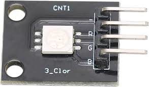
The KY-009 is a compact RGB LED module designed for creating vibrant and customizable lighting effects. It features three LEDs (Red, Green, and Blue) housed in a single package, allowing for the generation of a wide range of colors through Pulse Width Modulation (PWM). This module is ideal for projects requiring colorful lighting, such as decorative displays, status indicators, or interactive designs. Its small size and ease of use make it a popular choice for hobbyists and professionals alike.

Explore Projects Built with Ky-009

Use Cirkit Designer to design, explore, and prototype these projects online. Some projects support real-time simulation. Click "Open Project" to start designing instantly!
Arduino Nano Joystick-Controlled Bluetooth Module with Battery Power
Image of padelpro transmitter: A project utilizing Ky-009 in a practical application
This circuit is a wireless joystick controller that uses an Arduino Nano to read analog signals from a KY-023 Dual Axis Joystick Module and transmits the data via an HC-05 Bluetooth Module. The system is powered by a 18650 Li-Ion battery with a rocker switch for power control.
Cirkit Designer LogoOpen Project in Cirkit Designer
Arduino Nano-Based Wireless Joystick and Motion Controller
Image of hand gesture: A project utilizing Ky-009 in a practical application
This circuit features an Arduino Nano microcontroller interfaced with an HC-05 Bluetooth module, an MPU-6050 accelerometer/gyroscope, and a KY-023 Dual Axis Joystick Module. The Arduino Nano is powered by a 9V battery through a rocker switch and communicates with the HC-05 for Bluetooth connectivity, reads joystick positions from the KY-023 module via analog inputs, and communicates with the MPU-6050 over I2C to capture motion data. The circuit is likely designed for wireless control and motion sensing applications, such as a remote-controlled robot or a game controller.
Cirkit Designer LogoOpen Project in Cirkit Designer
ESP32-Based Security System with RFID and Laser Tripwire
Image of CPE doorlock system: A project utilizing Ky-009 in a practical application
This circuit is designed for a comprehensive security and access control system with motion detection, access via RFID, and a break-beam sensor. It includes a solenoid lock controlled by a relay, visual and audible alerts, and a robust power management system with solar and battery backup to ensure uninterrupted operation.
Cirkit Designer LogoOpen Project in Cirkit Designer
ESP32-Based Security System with RFID and Laser Intrusion Detection
Image of CPE doorlock system upgrade: A project utilizing Ky-009 in a practical application
This circuit is a security and access control system featuring motion detection, laser beam-break sensing, and RFID scanning, interfaced with a keypad and visual/audible indicators, powered by a solar-charged battery, and capable of controlling an electric lock via a relay.
Cirkit Designer LogoOpen Project in Cirkit Designer

Explore Projects Built with Ky-009

Use Cirkit Designer to design, explore, and prototype these projects online. Some projects support real-time simulation. Click "Open Project" to start designing instantly!
Image of padelpro transmitter: A project utilizing Ky-009 in a practical application
Arduino Nano Joystick-Controlled Bluetooth Module with Battery Power
This circuit is a wireless joystick controller that uses an Arduino Nano to read analog signals from a KY-023 Dual Axis Joystick Module and transmits the data via an HC-05 Bluetooth Module. The system is powered by a 18650 Li-Ion battery with a rocker switch for power control.
Cirkit Designer LogoOpen Project in Cirkit Designer
Image of hand gesture: A project utilizing Ky-009 in a practical application
Arduino Nano-Based Wireless Joystick and Motion Controller
This circuit features an Arduino Nano microcontroller interfaced with an HC-05 Bluetooth module, an MPU-6050 accelerometer/gyroscope, and a KY-023 Dual Axis Joystick Module. The Arduino Nano is powered by a 9V battery through a rocker switch and communicates with the HC-05 for Bluetooth connectivity, reads joystick positions from the KY-023 module via analog inputs, and communicates with the MPU-6050 over I2C to capture motion data. The circuit is likely designed for wireless control and motion sensing applications, such as a remote-controlled robot or a game controller.
Cirkit Designer LogoOpen Project in Cirkit Designer
Image of CPE doorlock system: A project utilizing Ky-009 in a practical application
ESP32-Based Security System with RFID and Laser Tripwire
This circuit is designed for a comprehensive security and access control system with motion detection, access via RFID, and a break-beam sensor. It includes a solenoid lock controlled by a relay, visual and audible alerts, and a robust power management system with solar and battery backup to ensure uninterrupted operation.
Cirkit Designer LogoOpen Project in Cirkit Designer
Image of CPE doorlock system upgrade: A project utilizing Ky-009 in a practical application
ESP32-Based Security System with RFID and Laser Intrusion Detection
This circuit is a security and access control system featuring motion detection, laser beam-break sensing, and RFID scanning, interfaced with a keypad and visual/audible indicators, powered by a solar-charged battery, and capable of controlling an electric lock via a relay.
Cirkit Designer LogoOpen Project in Cirkit Designer

Common Applications

  • Decorative lighting and displays
  • Status indicators for electronic devices
  • Interactive projects and prototypes
  • Educational projects for learning about PWM and color mixing

Technical Specifications

  • Operating Voltage: 5V DC
  • Current Consumption: ~20mA per LED (typical)
  • LED Colors: Red, Green, Blue
  • Control Method: PWM for each color channel
  • Dimensions: 18.5mm x 15mm x 2.5mm (approx.)
  • Connector Type: 4-pin header

Pin Configuration and Descriptions

Pin Number Pin Name Description
1 R Red LED anode (connect to PWM pin)
2 G Green LED anode (connect to PWM pin)
3 B Blue LED anode (connect to PWM pin)
4 GND Common cathode (connect to ground)

Usage Instructions

How to Use the KY-009 in a Circuit

  1. Power Supply: Connect the GND pin of the KY-009 module to the ground of your power source or microcontroller.
  2. PWM Control: Connect the R, G, and B pins to PWM-capable pins on your microcontroller. These pins control the brightness of the Red, Green, and Blue LEDs, respectively.
  3. Resistors: Use appropriate current-limiting resistors (typically 220Ω to 330Ω) in series with each LED pin to prevent overcurrent damage.
  4. Programming: Use PWM signals to adjust the brightness of each LED, mixing colors as needed.

Important Considerations

  • Ensure the total current draw does not exceed the microcontroller's pin current limits.
  • Use external transistors or MOSFETs if higher current is required for brighter LEDs.
  • Avoid connecting the module directly to a power source without resistors, as this may damage the LEDs.

Example Code for Arduino UNO

The following example demonstrates how to control the KY-009 module using an Arduino UNO. It cycles through different colors by adjusting the PWM signals.

// Define the PWM pins connected to the KY-009 module
const int redPin = 9;   // Red LED pin
const int greenPin = 10; // Green LED pin
const int bluePin = 11;  // Blue LED pin

void setup() {
  // Set the RGB pins as output
  pinMode(redPin, OUTPUT);
  pinMode(greenPin, OUTPUT);
  pinMode(bluePin, OUTPUT);
}

void loop() {
  // Set the LED to red
  analogWrite(redPin, 255);  // Full brightness for red
  analogWrite(greenPin, 0);  // Green off
  analogWrite(bluePin, 0);   // Blue off
  delay(1000);               // Wait 1 second

  // Set the LED to green
  analogWrite(redPin, 0);    // Red off
  analogWrite(greenPin, 255); // Full brightness for green
  analogWrite(bluePin, 0);   // Blue off
  delay(1000);               // Wait 1 second

  // Set the LED to blue
  analogWrite(redPin, 0);    // Red off
  analogWrite(greenPin, 0);  // Green off
  analogWrite(bluePin, 255); // Full brightness for blue
  delay(1000);               // Wait 1 second

  // Set the LED to white (all colors on)
  analogWrite(redPin, 255);  // Full brightness for red
  analogWrite(greenPin, 255); // Full brightness for green
  analogWrite(bluePin, 255); // Full brightness for blue
  delay(1000);               // Wait 1 second
}

Troubleshooting and FAQs

Common Issues

  1. LEDs Not Lighting Up:

    • Check the connections to ensure the R, G, and B pins are connected to PWM-capable pins.
    • Verify that the GND pin is properly connected to the ground of the power source.
    • Ensure current-limiting resistors are in place and of the correct value.
  2. Incorrect Colors:

    • Verify the PWM values being sent to each pin. Incorrect values can result in unexpected colors.
    • Check for loose or swapped connections between the module and the microcontroller.
  3. Dim or Flickering LEDs:

    • Ensure the power supply provides sufficient current for the module.
    • Check for poor solder joints or loose connections.

Tips for Troubleshooting

  • Use a multimeter to verify voltage levels at the module's pins.
  • Test each LED channel (R, G, B) individually by connecting it to a 5V source with a resistor.
  • If using an external power source, ensure it shares a common ground with the microcontroller.

By following this documentation, you can effectively integrate the KY-009 RGB LED module into your projects and create stunning lighting effects.