How to Use GSM/GPRS Module ROHS: Examples, Pinouts, and Specs
Introduction
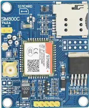
The GSM/GPRS Module ROHS (SIM800C_V4.2.4) is a compact and reliable device designed to enable communication over mobile networks. It supports GSM (Global System for Mobile Communications) and GPRS (General Packet Radio Service) technologies, allowing for voice, SMS, and data transmission. This module is compliant with ROHS (Restriction of Hazardous Substances) standards, ensuring it is free from hazardous materials, making it suitable for environmentally friendly applications.
Explore Projects Built with GSM/GPRS Module ROHS


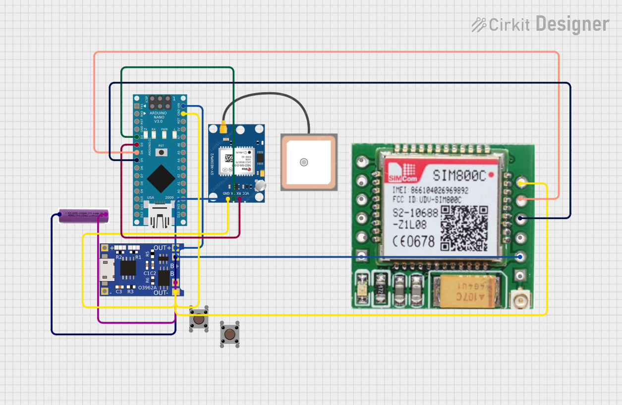
Explore Projects Built with GSM/GPRS Module ROHS
Common Applications and Use Cases
- IoT (Internet of Things) devices for remote monitoring and control
- Smart home automation systems
- Vehicle tracking and fleet management
- Industrial automation and telemetry
- SMS-based alert systems
- Wireless data transmission in embedded systems
Technical Specifications
Below are the key technical details of the SIM800C_V4.2.4 GSM/GPRS module:
| Parameter | Specification |
|---|---|
| Operating Voltage | 3.4V to 4.4V (Typical: 4.0V) |
| Operating Current | Idle: ~18mA, GPRS Transmission: ~100mA, Peak: ~2A |
| Frequency Bands | Quad-band: 850/900/1800/1900 MHz |
| Data Transmission | GPRS Class 12, up to 85.6 kbps |
| SMS Support | Text and PDU modes |
| Operating Temperature | -40°C to +85°C |
| Dimensions | 17.6mm x 15.7mm x 2.3mm |
| Compliance | ROHS compliant |
Pin Configuration and Descriptions
The SIM800C_V4.2.4 module has multiple pins for power, communication, and control. Below is the pin configuration:
| Pin Name | Pin Number | Description |
|---|---|---|
| VCC | 1 | Power supply input (3.4V to 4.4V) |
| GND | 2 | Ground connection |
| TXD | 3 | UART Transmit Data (connect to RXD of microcontroller) |
| RXD | 4 | UART Receive Data (connect to TXD of microcontroller) |
| DTR | 5 | Data Terminal Ready (used for sleep mode control) |
| RST | 6 | Reset pin (active low, used to reset the module) |
| NETLIGHT | 7 | Network status indicator (blinks to indicate network activity) |
| MIC+ | 8 | Microphone positive input |
| MIC- | 9 | Microphone negative input |
| SPK+ | 10 | Speaker positive output |
| SPK- | 11 | Speaker negative output |
| ANT | 12 | Antenna connection |
Usage Instructions
How to Use the Component in a Circuit
- Power Supply: Ensure the module is powered with a stable voltage between 3.4V and 4.4V. A capacitor (e.g., 100µF) is recommended near the power pins to handle peak current demands.
- UART Communication: Connect the TXD and RXD pins to the corresponding RXD and TXD pins of a microcontroller (e.g., Arduino UNO). Use a logic level converter if the microcontroller operates at 5V logic.
- Antenna: Attach a compatible GSM antenna to the ANT pin for proper signal reception.
- Network Status: Monitor the NETLIGHT pin to check the module's network status (e.g., blinking patterns indicate connection status).
- SIM Card: Insert a valid SIM card into the module's SIM card slot.
Important Considerations and Best Practices
- Power Supply: Use a power source capable of supplying at least 2A to handle the module's peak current requirements.
- Antenna Placement: Place the antenna away from other electronic components to avoid interference.
- UART Baud Rate: The default baud rate is 9600 bps. Configure your microcontroller to match this baud rate.
- Sleep Mode: Use the DTR pin to enable sleep mode for power-saving applications.
- Reset: Use the RST pin to reset the module if it becomes unresponsive.
Example: Connecting to an Arduino UNO
Below is an example of how to send an SMS using the SIM800C_V4.2.4 module with an Arduino UNO:
Circuit Connections
- SIM800C TXD → Arduino RX (Pin 0)
- SIM800C RXD → Arduino TX (Pin 1)
- SIM800C VCC → 5V Power Supply (via voltage regulator)
- SIM800C GND → Arduino GND
Arduino Code
#include <SoftwareSerial.h>

// Define RX and TX pins for SoftwareSerial
SoftwareSerial SIM800C(10, 11); // RX = Pin 10, TX = Pin 11

void setup() {
  // Initialize serial communication with the module
  SIM800C.begin(9600); // Set baud rate to 9600
  Serial.begin(9600);  // For debugging via Serial Monitor

  delay(1000); // Wait for the module to initialize

  // Send SMS command
  sendSMS("+1234567890", "Hello, this is a test message from SIM800C!");
}

void loop() {
  // Nothing to do in the loop
}

void sendSMS(String phoneNumber, String message) {
  SIM800C.println("AT"); // Check communication with the module
  delay(1000);

  SIM800C.println("AT+CMGF=1"); // Set SMS mode to text
  delay(1000);

  SIM800C.print("AT+CMGS=\""); // Start SMS command
  SIM800C.print(phoneNumber);  // Add recipient phone number
  SIM800C.println("\"");
  delay(1000);

  SIM800C.print(message); // Add SMS content
  delay(1000);

  SIM800C.write(26); // Send Ctrl+Z to send the SMS
  delay(5000); // Wait for the SMS to be sent
}
Troubleshooting and FAQs
Common Issues and Solutions
Module Not Responding to AT Commands
- Ensure the module is powered correctly and the voltage is within the specified range.
- Check the UART connections (TXD and RXD) and ensure the baud rate matches.
No Network Connection
- Verify that the SIM card is inserted correctly and has an active plan.
- Check the antenna connection and ensure the module is in an area with good network coverage.
SMS Not Sending
- Ensure the module is registered on the network (check NETLIGHT pin status).
- Verify the phone number format (e.g., include the country code).
High Power Consumption
- Use the DTR pin to enable sleep mode when the module is idle.
- Ensure the power supply can handle peak current demands.
FAQs
Q: Can the module be powered directly from a 5V source?
A: No, the module requires a voltage between 3.4V and 4.4V. Use a voltage regulator if your power source is 5V.
Q: What is the default baud rate of the module?
A: The default baud rate is 9600 bps.
Q: How can I check if the module is connected to the network?
A: Monitor the NETLIGHT pin. Refer to the module's datasheet for the blinking patterns indicating network status.
Q: Can I use this module for voice calls?
A: Yes, the module supports voice calls. Connect a microphone and speaker to the MIC+/- and SPK+/- pins, respectively.