How to Use Driver: Examples, Pinouts, and Specs
Introduction
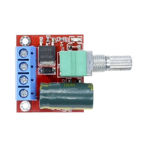
A driver is an electronic component designed to provide the necessary current and voltage to control other components, such as transistors, motors, LEDs, or relays. Drivers act as intermediaries between control circuits (e.g., microcontrollers) and high-power devices, ensuring proper operation and performance. They are essential in applications where the control signal is insufficient to directly drive the load.
Explore Projects Built with Driver
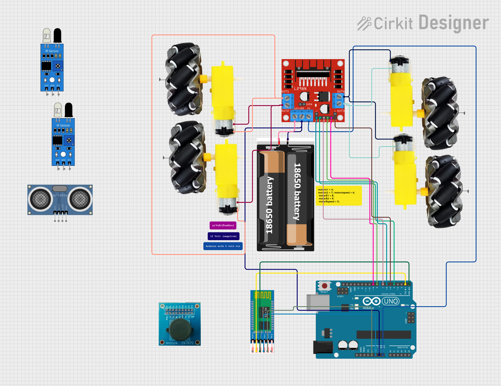
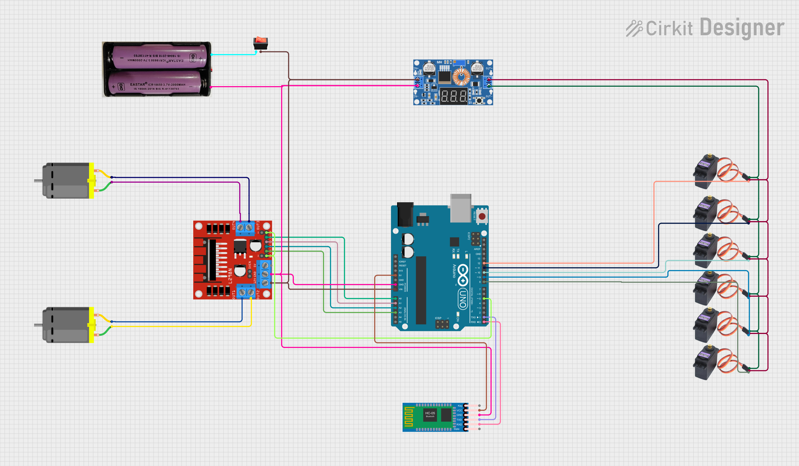
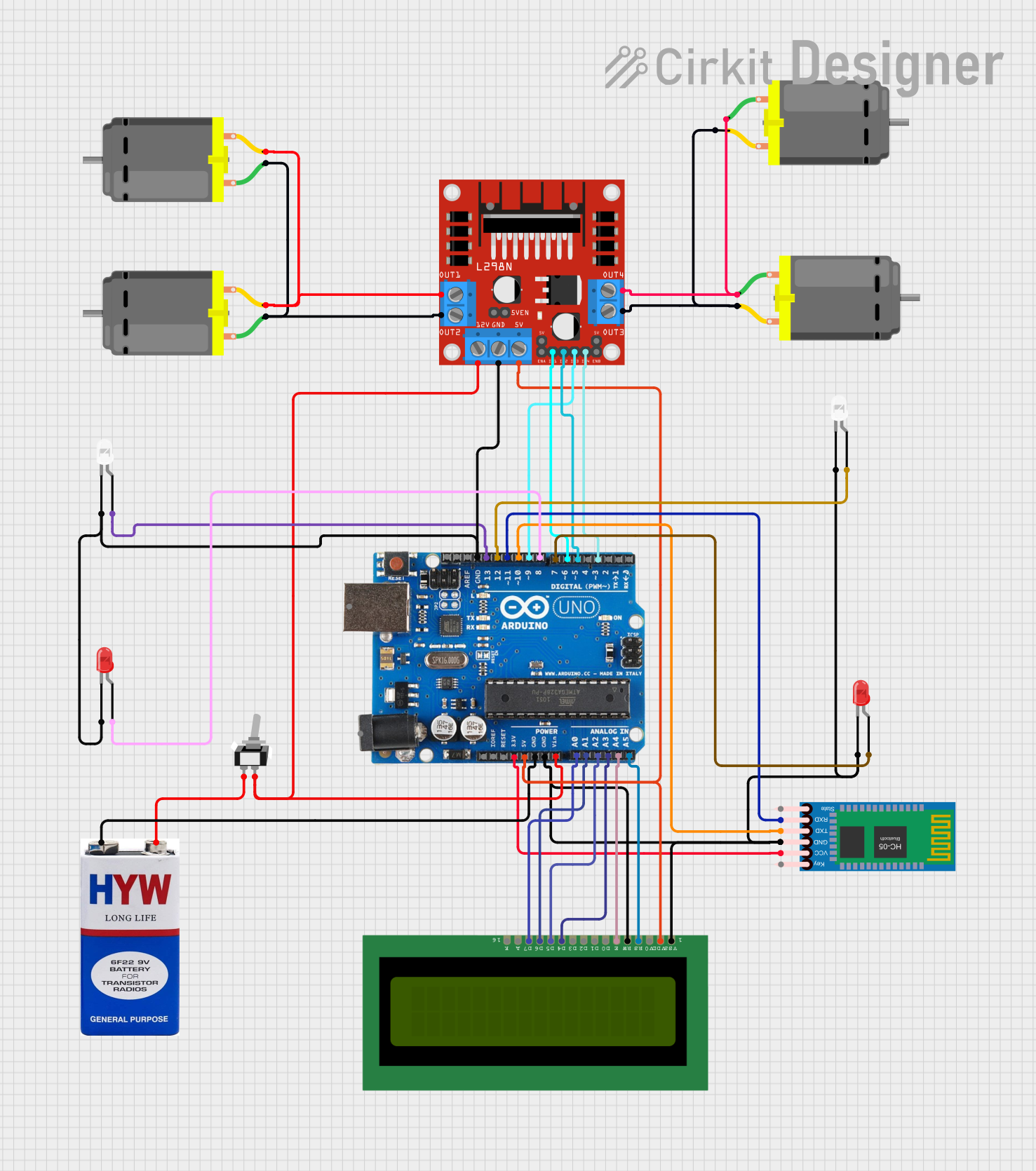
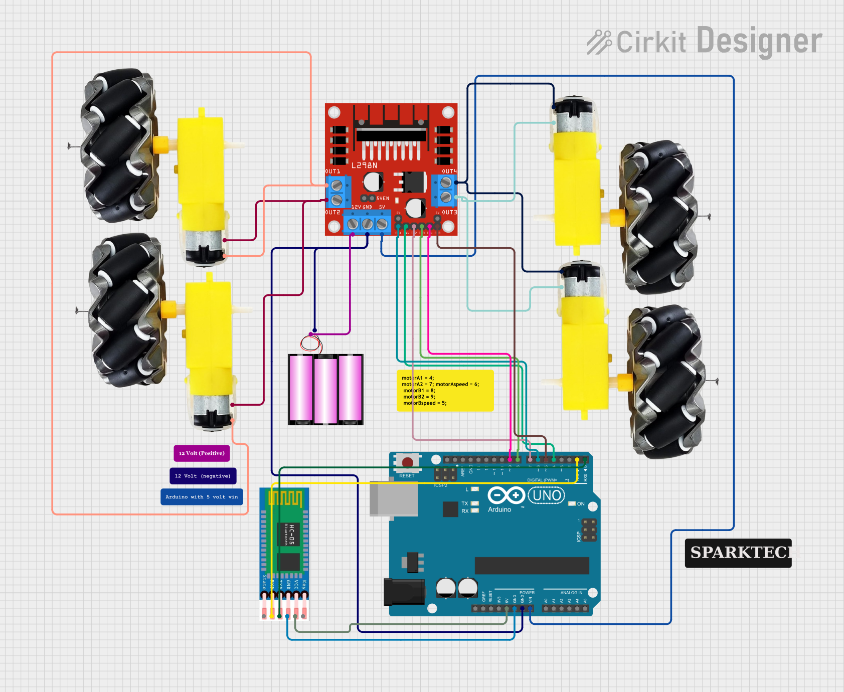
Explore Projects Built with Driver
Common Applications and Use Cases
- Motor control in robotics and industrial automation
- Driving high-power LEDs in lighting systems
- Switching relays in home automation and industrial systems
- Amplifying control signals for transistors in power electronics
- Controlling stepper motors in 3D printers and CNC machines
Technical Specifications
The technical specifications of a driver vary depending on its type and intended application. Below are general specifications for a typical motor driver IC (e.g., L298N):
Key Technical Details
- Operating Voltage: 5V to 46V (depending on the driver type)
- Output Current: Up to 2A per channel (for motor drivers)
- Logic Voltage: 3.3V or 5V (compatible with most microcontrollers)
- Control Inputs: PWM and direction control pins
- Thermal Protection: Built-in over-temperature shutdown
- Current Sensing: Optional pins for monitoring current
Pin Configuration and Descriptions
Below is an example pinout for a dual H-bridge motor driver IC (L298N):
| Pin Name | Pin Number | Description |
|---|---|---|
| IN1 | 1 | Input pin to control the direction of Motor A (logic HIGH or LOW) |
| IN2 | 2 | Input pin to control the direction of Motor A (logic HIGH or LOW) |
| ENA | 3 | Enable pin for Motor A (PWM signal for speed control) |
| OUT1 | 4 | Output pin connected to one terminal of Motor A |
| OUT2 | 5 | Output pin connected to the other terminal of Motor A |
| GND | 6 | Ground connection |
| VCC | 7 | Supply voltage for the motor (e.g., 12V or 24V) |
| IN3 | 8 | Input pin to control the direction of Motor B (logic HIGH or LOW) |
| IN4 | 9 | Input pin to control the direction of Motor B (logic HIGH or LOW) |
| ENB | 10 | Enable pin for Motor B (PWM signal for speed control) |
| OUT3 | 11 | Output pin connected to one terminal of Motor B |
| OUT4 | 12 | Output pin connected to the other terminal of Motor B |
Usage Instructions
How to Use the Component in a Circuit
Power the Driver:
- Connect the VCC pin to the appropriate supply voltage for the load (e.g., 12V for motors).
- Connect the GND pin to the ground of the power supply and the control circuit.
Connect the Load:
- For motor drivers, connect the motor terminals to the OUT1/OUT2 or OUT3/OUT4 pins.
- For LED drivers, connect the LED anode to the output pin and the cathode to ground.
Control the Driver:
- Use the IN1/IN2 (or IN3/IN4) pins to set the direction of the motor or the state of the load.
- Apply a PWM signal to the ENA/ENB pins to control the speed or brightness of the load.
Interface with a Microcontroller:
- Connect the control pins (IN1, IN2, ENA, etc.) to the GPIO pins of a microcontroller (e.g., Arduino UNO).
- Ensure the logic voltage levels are compatible (3.3V or 5V).
Important Considerations and Best Practices
- Heat Dissipation: Use a heat sink or cooling fan if the driver operates at high currents for extended periods.
- Current Limits: Ensure the load current does not exceed the driver's maximum current rating.
- Decoupling Capacitors: Add capacitors near the power supply pins to reduce noise and voltage spikes.
- Protection Diodes: For inductive loads like motors, ensure the driver has built-in flyback diodes or add external ones.
Example Code for Arduino UNO
Below is an example of how to control a DC motor using an L298N driver and an Arduino UNO:
// Define motor control pins
const int IN1 = 7;  // Direction control pin 1 for Motor A
const int IN2 = 8;  // Direction control pin 2 for Motor A
const int ENA = 9;  // PWM speed control pin for Motor A

void setup() {
  // Set motor control pins as outputs
  pinMode(IN1, OUTPUT);
  pinMode(IN2, OUTPUT);
  pinMode(ENA, OUTPUT);
}

void loop() {
  // Rotate motor forward
  digitalWrite(IN1, HIGH);  // Set IN1 HIGH
  digitalWrite(IN2, LOW);   // Set IN2 LOW
  analogWrite(ENA, 128);    // Set speed to 50% (PWM value: 128 out of 255)
  delay(2000);              // Run for 2 seconds

  // Stop motor
  digitalWrite(IN1, LOW);   // Set IN1 LOW
  digitalWrite(IN2, LOW);   // Set IN2 LOW
  delay(1000);              // Wait for 1 second

  // Rotate motor backward
  digitalWrite(IN1, LOW);   // Set IN1 LOW
  digitalWrite(IN2, HIGH);  // Set IN2 HIGH
  analogWrite(ENA, 128);    // Set speed to 50% (PWM value: 128 out of 255)
  delay(2000);              // Run for 2 seconds

  // Stop motor
  digitalWrite(IN1, LOW);   // Set IN1 LOW
  digitalWrite(IN2, LOW);   // Set IN2 LOW
  delay(1000);              // Wait for 1 second
}
Troubleshooting and FAQs
Common Issues Users Might Face
Motor Does Not Spin:
- Check the power supply voltage and current rating.
- Verify the connections to the motor and driver pins.
- Ensure the control signals (IN1, IN2, ENA) are correctly configured.
Driver Overheats:
- Ensure the load current is within the driver's rated capacity.
- Add a heat sink or cooling fan to dissipate heat.
Erratic Motor Behavior:
- Check for loose or faulty connections.
- Add decoupling capacitors to the power supply to reduce noise.
Microcontroller Not Responding:
- Verify that the driver's logic voltage matches the microcontroller's GPIO voltage.
- Check for proper grounding between the driver and the microcontroller.
Solutions and Tips for Troubleshooting
- Use a multimeter to measure voltages at key points in the circuit.
- Test the driver with a simple load (e.g., an LED) before connecting a motor.
- Consult the datasheet of the specific driver IC for detailed information and recommendations.