How to Use Adafruit FONA - Mini Cellular GSM SMA Breakout: Examples, Pinouts, and Specs
Introduction
The Adafruit FONA - Mini Cellular GSM SMA Breakout is a versatile and compact breakout board designed to integrate cellular communication into your microcontroller projects. It allows for voice calls, SMS messages, and GPRS data connectivity, making it ideal for a wide range of applications such as remote monitoring, IoT devices, and mobile communication projects.
Explore Projects Built with Adafruit FONA - Mini Cellular GSM SMA Breakout
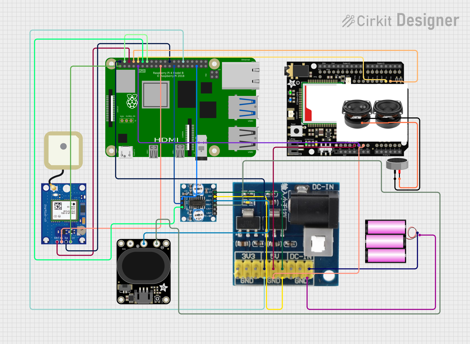
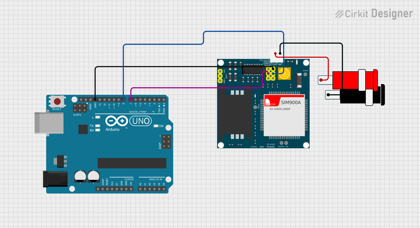

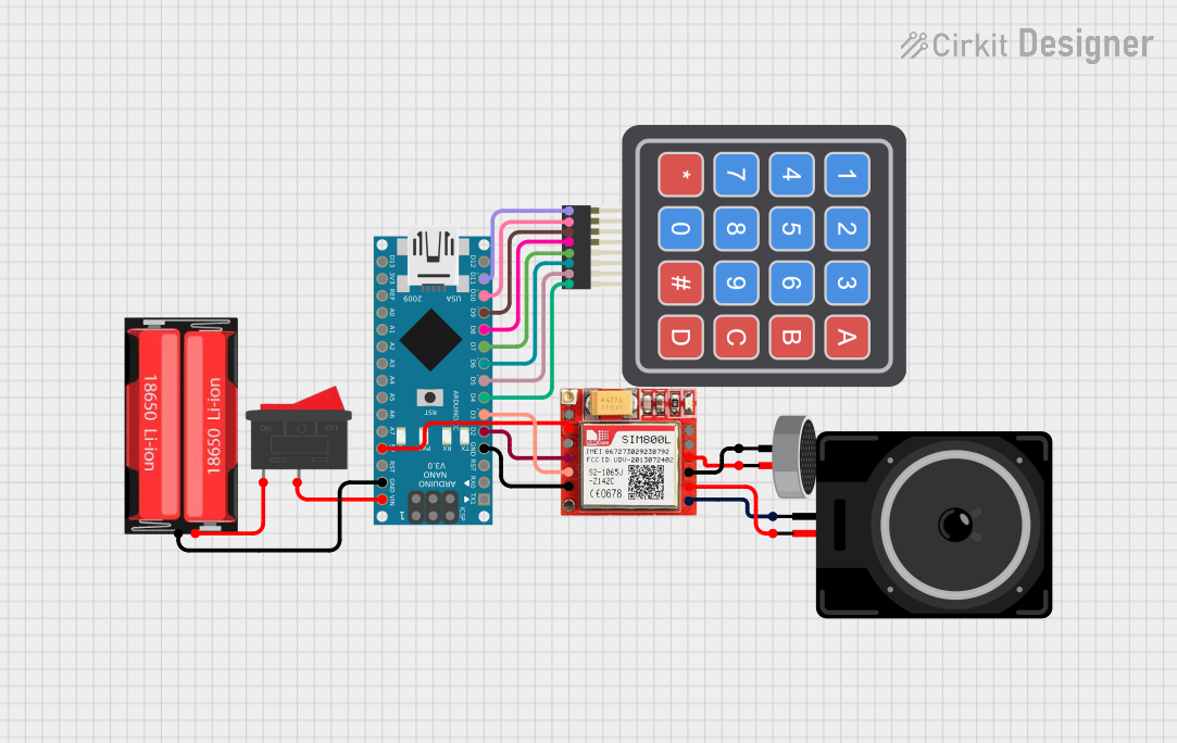
Explore Projects Built with Adafruit FONA - Mini Cellular GSM SMA Breakout
Common Applications and Use Cases
- Remote data logging and telemetry
- SMS-based remote control
- Voice communication for embedded systems
- IoT devices with cellular connectivity
- Asset tracking and fleet management
Technical Specifications
Key Technical Details
- Frequency Bands: Quad-band 850/900/1800/1900MHz
- Supply Voltage: 3.4-4.4VDC
- Logic Level: 2.8V logic, but is also 5V compliant
- Current Draw: 250mA during cellular operations
- Antenna Interface: SMA connector for external GSM antenna
- SIM Card Interface: 2FF SIM card slot
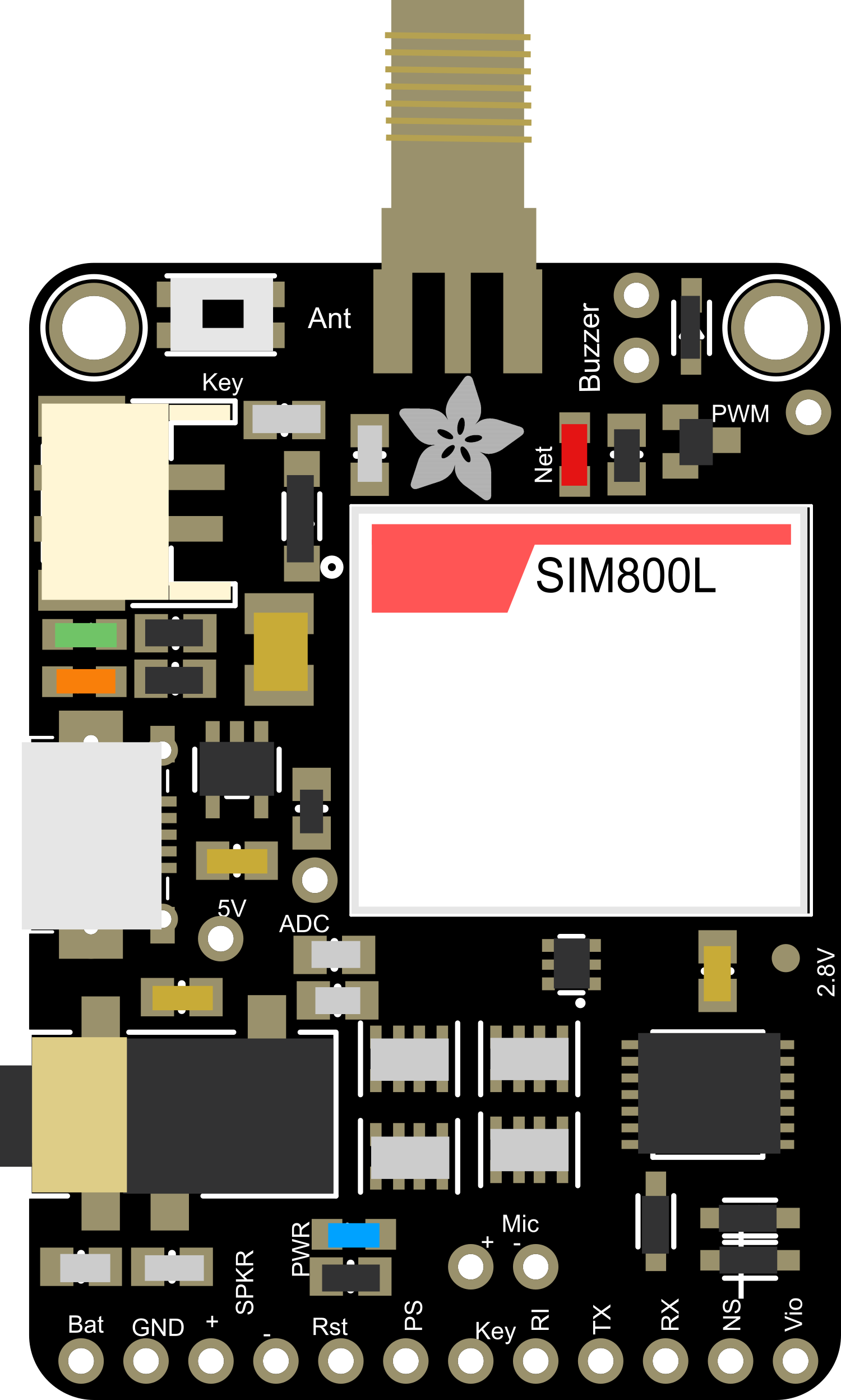
Pin Configuration and Descriptions
| Pin Number | Name | Description |
|---|---|---|
| 1 | Vio | Power supply for logic level (2.8V to 5V) |
| 2 | GND | Ground connection |
| 3 | RST | Reset pin (active low) |
| 4 | RX | UART receive pin |
| 5 | TX | UART transmit pin |
| 6 | Key | Power on/off status pin |
| 7 | PS | Power status pin |
| 8 | NS | Network status indicator |
| 9 | RI | Ring indicator for incoming calls and SMS |
| 10 | NC | No connection |
Usage Instructions
How to Use the Component in a Circuit
- Power Supply: Connect a 3.4-4.4VDC power source to the Vio and GND pins.
- Antenna: Attach an SMA antenna to the SMA connector to ensure proper GSM signal reception.
- SIM Card: Insert a 2FF SIM card into the SIM card slot.
- Microcontroller Connection: Connect the RX and TX pins to the corresponding TX and RX pins on your microcontroller, ensuring proper logic level matching.
- Power On: To power on the module, pull the Key pin to ground for a brief moment.
Important Considerations and Best Practices
- Ensure that the power supply can provide sufficient current for the module during transmission.
- Use a level shifter if your microcontroller operates at a different logic level than the module.
- Place the antenna in a position with minimal obstructions to maintain a strong GSM signal.
- Always power down the module before inserting or removing the SIM card.
Example Code for Arduino UNO
#include <SoftwareSerial.h>

SoftwareSerial fonaSerial(2, 3); // RX, TX
uint8_t readline(char *buff, uint8_t maxbuff, uint16_t timeout = 0);

void setup() {
  fonaSerial.begin(4800);
  if (!fona.begin(fonaSerial)) {
    Serial.println(F("Couldn't find FONA"));
    while (1);
  }
  Serial.println(F("FONA is OK"));
  // Make a voice call
  fona.callPhone("1234567890");
}

void loop() {
  // Check for incoming calls
  char callerIDbuffer[32];  // we'll store the SMS sender number in here
  if (fona.incomingCallNumber(callerIDbuffer)) {
    Serial.print(F("Incoming call from "));
    Serial.println(callerIDbuffer);
  }
}

// Read a line from the FONA's UART
uint8_t readline(char *buff, uint8_t maxbuff, uint16_t timeout) {
  uint16_t buffidx = 0;
  boolean timeoutvalid = true;
  if (timeout == 0) timeoutvalid = false;

  while (true) {
    if (buffidx > maxbuff) {
      // Buffer full
      break;
    }

    while (fonaSerial.available()) {
      char c = fonaSerial.read();

      // End of line character or newline
      if (c == '\r' || c == '\n') {
        if (buffidx == 0) {  // a newline with no data?
          continue;           // just ignore it
        }
        timeout = 0;         // the end of the line
        break;
      }
      buff[buffidx] = c;
      buffidx++;
    }

    if (timeoutvalid && timeout > 0) {
      delay(1);
      timeout--;
      if (timeout == 0) {
        break;
      }
    }
  }
  buff[buffidx] = '\0';  // null terminate the string
  return buffidx;
}
Troubleshooting and FAQs
Common Issues Users Might Face
- No Network Connection: Ensure the antenna is properly connected and the SIM card is active and has a data plan.
- Module Does Not Power On: Check the power supply and ensure the Key pin has been pulsed correctly.
- Serial Communication Issues: Verify the baud rate and logic levels match between the FONA module and the microcontroller.
Solutions and Tips for Troubleshooting
- Power Supply Issues: Use a multimeter to check the voltage at the Vio pin.
- Antenna Placement: Try repositioning the antenna or moving the entire setup to a location with better signal reception.
- SIM Card Activation: Confirm that the SIM card is activated with the carrier and properly inserted into the module.
FAQs
Q: Can I use the Adafruit FONA with a 5V microcontroller? A: Yes, the FONA is 5V tolerant on the UART pins, but ensure that the Vio pin is supplied with a voltage within the specified range.
Q: How do I send an SMS using the FONA?
A: You can use the fona.sendSMS(char *number, char *message) function to send an SMS to the specified number.
Q: What should I do if I'm not getting a GSM signal? A: Check the antenna connection, ensure the SIM card is active, and verify that you are in an area with GSM coverage.
Q: How can I reduce power consumption when the module is not in use? A: You can put the FONA into sleep mode by using the appropriate AT command or controlling the power key pin.