How to Use Male plug: Examples, Pinouts, and Specs
Introduction
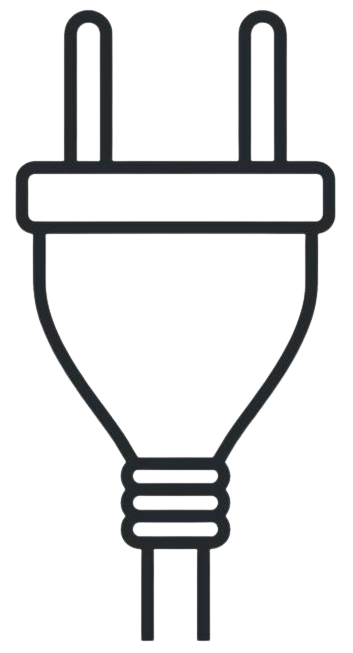
The male plug is a type of electrical connector characterized by protruding pins designed to fit into a corresponding female socket. It facilitates the transmission of electrical power or signals between devices or components. Male plugs are widely used in various applications, including power supplies, audio/video connections, and data transmission.
Explore Projects Built with Male plug

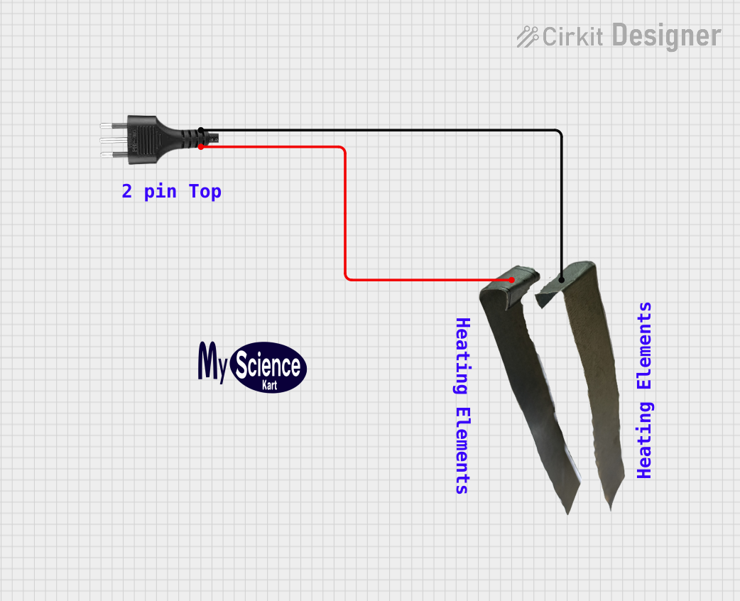


Explore Projects Built with Male plug
Common Applications and Use Cases
- Power connections for household appliances and electronic devices
- Audio and video equipment, such as headphones and AV cables
- Data communication in computer peripherals and networking
- Prototyping and breadboard connections in electronics projects
Technical Specifications
The technical specifications of a male plug can vary depending on its type and intended application. Below are general specifications for a standard male plug:
General Specifications
| Parameter | Value/Range |
|---|---|
| Voltage Rating | 5V to 250V (depending on type) |
| Current Rating | 0.5A to 15A (depending on type) |
| Pin Material | Brass, copper, or gold-plated metal |
| Insulation Material | Plastic, rubber, or thermoplastic |
| Operating Temperature | -20°C to 70°C |
Pin Configuration and Descriptions
The pin configuration of a male plug depends on its type. Below is an example for a 3-pin male plug commonly used in AC power connections:
| Pin Number | Name | Description |
|---|---|---|
| 1 | Live (L) | Carries the live current from the power source. |
| 2 | Neutral (N) | Completes the circuit by returning current. |
| 3 | Ground (G) | Provides a safety path for fault currents. |
For other types of male plugs, such as audio jacks or data connectors, the pin configuration will differ.
Usage Instructions
How to Use the Male Plug in a Circuit
- Identify the Pinout: Refer to the pin configuration table to understand the function of each pin.
- Connect to the Female Socket: Align the male plug with the corresponding female socket and insert it securely.
- Ensure Proper Insulation: Verify that the insulation material is intact to prevent short circuits or electric shocks.
- Test the Connection: Use a multimeter to check for continuity and ensure proper electrical contact.
Important Considerations and Best Practices
- Voltage and Current Ratings: Always ensure the male plug is rated for the voltage and current of your application to avoid overheating or damage.
- Secure Connections: Ensure the male plug is firmly inserted into the female socket to prevent loose connections.
- Avoid Overloading: Do not exceed the maximum current rating of the male plug.
- Inspect for Damage: Regularly check the pins and insulation for wear or damage.
Example: Using a Male Plug with an Arduino UNO
If you are using a male plug to connect a power supply to an Arduino UNO, follow these steps:
- Identify the positive (VCC) and negative (GND) terminals of the male plug.
- Connect the positive terminal to the Arduino's VIN pin and the negative terminal to the GND pin.
- Ensure the power supply voltage matches the Arduino's input voltage range (7-12V).
// Example code to blink an LED on Arduino UNO
// Ensure the male plug is properly connected to the Arduino's power input

int ledPin = 13; // Pin connected to the onboard LED

void setup() {
  pinMode(ledPin, OUTPUT); // Set the LED pin as an output
}

void loop() {
  digitalWrite(ledPin, HIGH); // Turn the LED on
  delay(1000);                // Wait for 1 second
  digitalWrite(ledPin, LOW);  // Turn the LED off
  delay(1000);                // Wait for 1 second
}
Troubleshooting and FAQs
Common Issues
- Loose Connection: The male plug does not fit securely into the female socket.
- Solution: Check for debris or damage in the socket and ensure the plug is properly aligned.
- Overheating: The male plug becomes hot during use.
- Solution: Verify that the plug is not exceeding its current rating and inspect for short circuits.
- No Signal or Power: The connected device does not receive power or signals.
- Solution: Use a multimeter to check for continuity and ensure proper pin connections.
FAQs
Q: Can I use a male plug with a higher voltage rating than required?
A: Yes, a higher voltage rating is acceptable as long as the current rating is not exceeded.
Q: How do I clean the pins of a male plug?
A: Use a soft cloth or a small brush with isopropyl alcohol to clean the pins. Avoid abrasive materials that may damage the surface.
Q: Can I repair a damaged male plug?
A: Minor repairs, such as replacing a broken pin, may be possible. However, for safety-critical applications, it is recommended to replace the plug entirely.