How to Use MOSFET Drivkort 4-kan 50V 10A: Examples, Pinouts, and Specs
Introduction
The MOSFET Drivkort 4-kan 50V 10A (Manufacturer Part ID: EKM014 - UCC27524) is a 4-channel MOSFET driver board designed by Electrokit. It is capable of handling up to 50V and 10A per channel, making it ideal for controlling high-power loads such as motors, LEDs, and heating elements. This driver board allows low-power control signals, such as those from microcontrollers, to efficiently drive high-power devices.
Explore Projects Built with MOSFET Drivkort 4-kan 50V 10A


Explore Projects Built with MOSFET Drivkort 4-kan 50V 10A
Common Applications and Use Cases
- Driving high-power DC motors
- Controlling high-current LED arrays
- Switching heating elements in industrial applications
- General-purpose high-power switching in automation systems
- Interfacing with microcontrollers like Arduino, Raspberry Pi, or other logic-level devices
Technical Specifications
The following are the key technical details of the MOSFET driver board:
| Parameter | Value |
|---|---|
| Input Voltage (Logic) | 3.3V to 5V |
| Output Voltage (Load) | Up to 50V |
| Maximum Output Current | 10A per channel |
| Number of Channels | 4 |
| MOSFET Driver IC | UCC27524 |
| Switching Frequency | Up to 1 MHz |
| Board Dimensions | 50mm x 50mm |
| Operating Temperature | -40°C to +125°C |
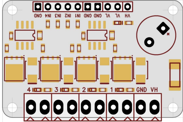
Pin Configuration and Descriptions
The MOSFET driver board has the following pinout:
Input Side (Logic Control)
| Pin | Name | Description |
|---|---|---|
| 1 | IN1 | Control signal for Channel 1 (3.3V or 5V logic) |
| 2 | IN2 | Control signal for Channel 2 (3.3V or 5V logic) |
| 3 | IN3 | Control signal for Channel 3 (3.3V or 5V logic) |
| 4 | IN4 | Control signal for Channel 4 (3.3V or 5V logic) |
| 5 | GND | Ground connection for logic signals |
| 6 | VCC | Power supply for logic signals (3.3V to 5V) |
Output Side (Load Control)
| Pin | Name | Description |
|---|---|---|
| 1 | OUT1 | Output for Channel 1 (connect to load) |
| 2 | OUT2 | Output for Channel 2 (connect to load) |
| 3 | OUT3 | Output for Channel 3 (connect to load) |
| 4 | OUT4 | Output for Channel 4 (connect to load) |
| 5 | GND | Ground connection for load |
| 6 | VIN | Power supply for the load (up to 50V) |
Usage Instructions
How to Use the Component in a Circuit
Power Connections:
- Connect the VIN pin to the positive terminal of your load power supply (up to 50V).
- Connect the GND pin to the ground of your load power supply.
- Connect the VCC pin to the power supply for the logic signals (3.3V or 5V).
- Ensure that the ground of the logic power supply is connected to the ground of the load power supply.
Control Signals:
- Connect the control signals (e.g., from a microcontroller) to the IN1, IN2, IN3, and IN4 pins.
- Use 3.3V or 5V logic levels to control the MOSFETs.
Load Connections:
- Connect your load (e.g., motor, LED array) to the OUT1, OUT2, OUT3, and OUT4 pins as needed.
Testing:
- Apply the appropriate control signals to the input pins and verify that the load is switching on and off as expected.
Important Considerations and Best Practices
- Ensure that the load does not exceed the maximum current rating of 10A per channel.
- Use proper heat dissipation methods (e.g., heatsinks) if operating at high currents for extended periods.
- Avoid short circuits between the output pins and ground or power supply.
- Use decoupling capacitors near the power supply pins to reduce noise and improve stability.
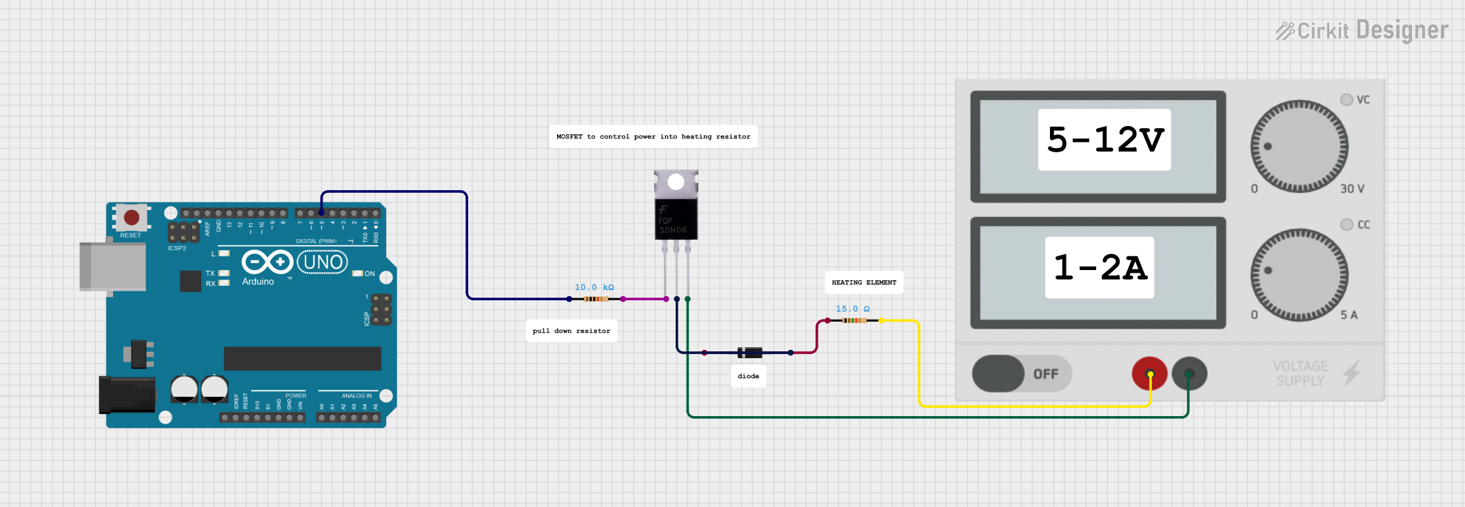
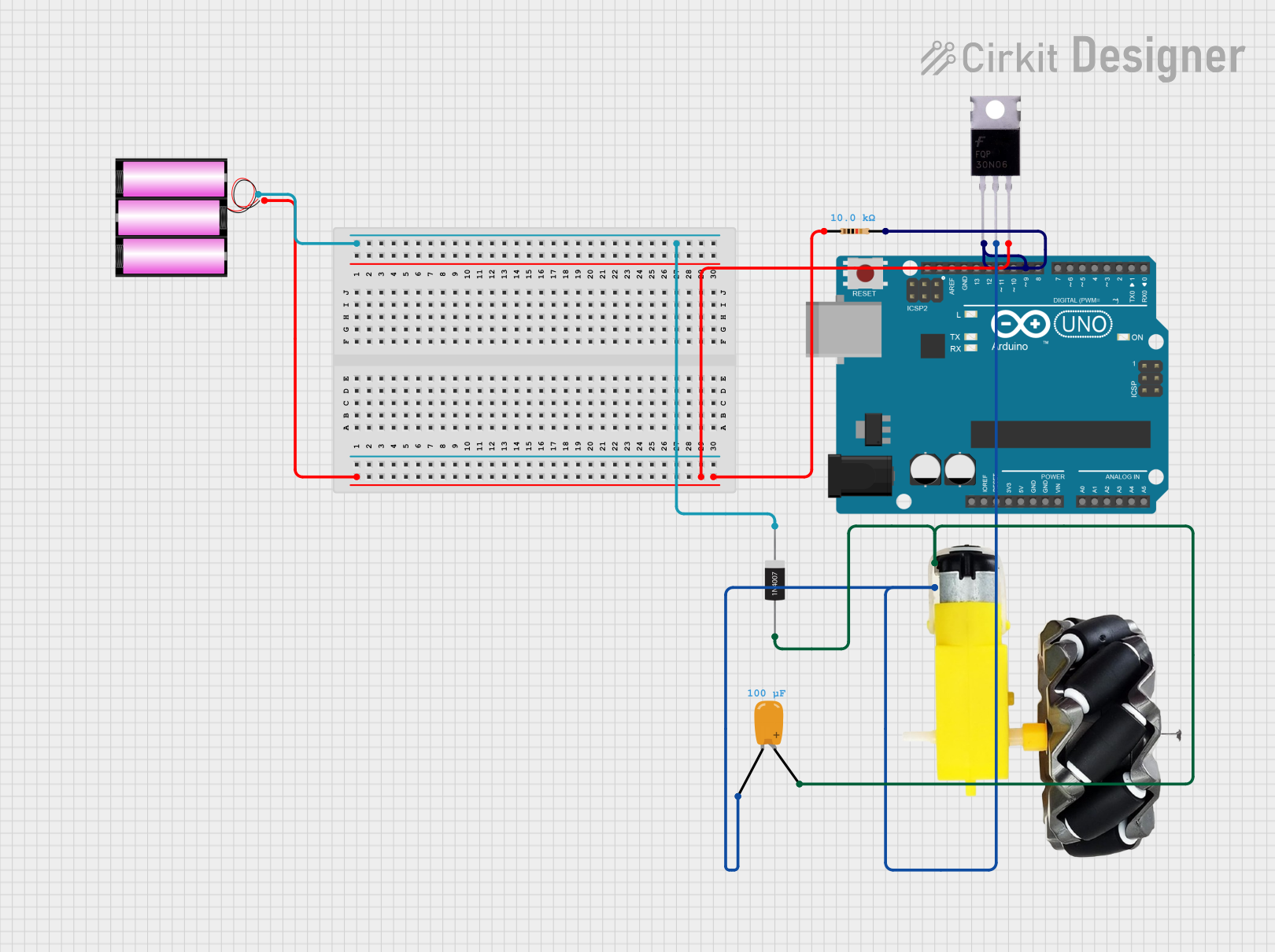
Example: Using with Arduino UNO
Below is an example of how to control a motor connected to Channel 1 using an Arduino UNO:
// Define the control pin for Channel 1
const int controlPin1 = 9;

void setup() {
  // Set the control pin as an output
  pinMode(controlPin1, OUTPUT);
}

void loop() {
  // Turn the motor ON
  digitalWrite(controlPin1, HIGH);
  delay(1000); // Keep the motor ON for 1 second

  // Turn the motor OFF
  digitalWrite(controlPin1, LOW);
  delay(1000); // Keep the motor OFF for 1 second
}
Troubleshooting and FAQs
Common Issues and Solutions
The load is not turning on:
- Verify that the control signal voltage matches the logic level (3.3V or 5V).
- Check the power supply connections for both the logic and load sides.
- Ensure that the load is properly connected to the output pins.
The MOSFET driver board overheats:
- Ensure that the load current does not exceed 10A per channel.
- Use a heatsink or active cooling if operating at high currents.
The load behaves erratically:
- Check for noise or instability in the power supply.
- Add decoupling capacitors near the power supply pins.
The board does not respond to control signals:
- Verify that the ground of the logic power supply is connected to the ground of the load power supply.
- Ensure that the control signals are properly connected to the input pins.
FAQs
Q: Can I use this board to control an AC load?
A: No, this board is designed for DC loads only. For AC loads, consider using a relay or a solid-state relay.
Q: What happens if I exceed the maximum current rating?
A: Exceeding the 10A per channel limit can damage the MOSFETs and the driver IC. Always ensure that your load stays within the specified limits.
Q: Can I use this board with a 12V logic signal?
A: No, the logic input voltage must be between 3.3V and 5V. Using higher voltages can damage the driver IC.
Q: Is it possible to control all four channels independently?
A: Yes, each channel has its own control input, allowing independent operation of all four channels.