How to Use LoRa E32: Examples, Pinouts, and Specs
Introduction
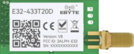
The LoRa E32 (433T20D) is a long-range, low-power wireless communication module manufactured by EBYTE. It leverages LoRa (Long Range) technology to enable data transmission over distances of several kilometers, even in environments with significant obstacles. Operating in the 433MHz frequency band, this module is ideal for Internet of Things (IoT) applications, offering reliable communication with minimal power consumption.
Explore Projects Built with LoRa E32
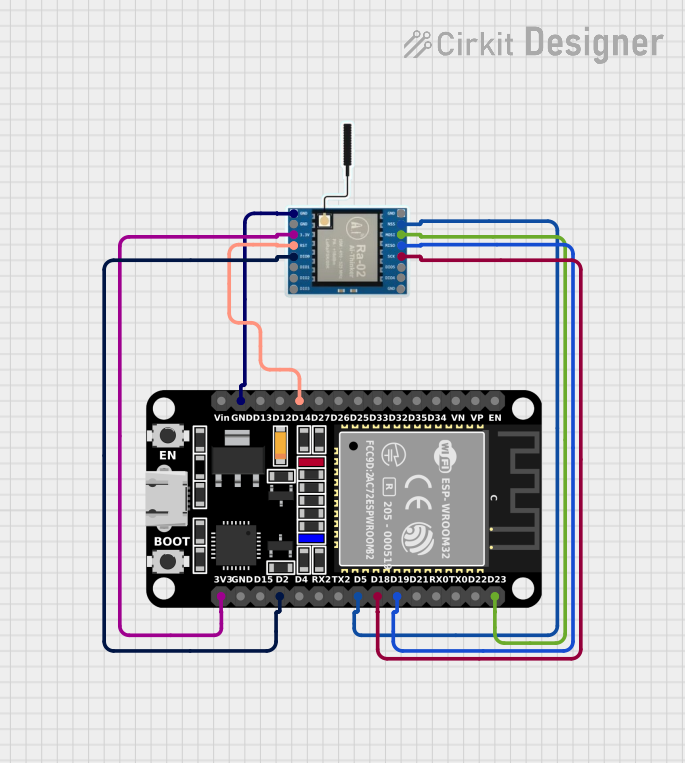
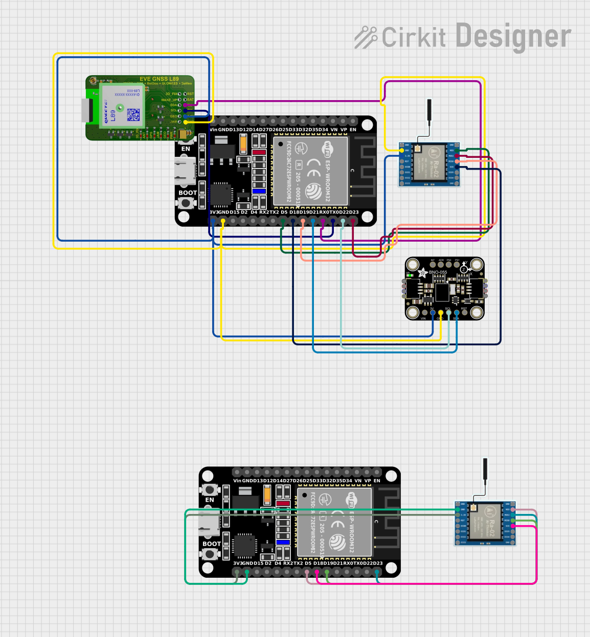
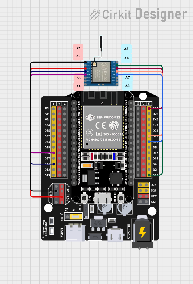

Explore Projects Built with LoRa E32
Common Applications and Use Cases
- Smart agriculture (e.g., soil moisture monitoring, weather stations)
- Industrial automation and control systems
- Smart cities (e.g., parking sensors, streetlight control)
- Remote monitoring and telemetry
- Home automation and security systems
- Wireless sensor networks
Technical Specifications
The LoRa E32 (433T20D) module is designed to provide robust and efficient communication. Below are its key technical specifications:
| Parameter | Value |
|---|---|
| Frequency Band | 433 MHz |
| Communication Range | Up to 5 km (line of sight) |
| Transmit Power | 20 dBm (100 mW) |
| Sensitivity | -139 dBm |
| Modulation | LoRa |
| Data Rate | 0.3 kbps to 19.2 kbps |
| Operating Voltage | 2.3V to 5.5V |
| Operating Current | 120 mA (transmit), 16 mA (receive) |
| Sleep Current | < 2 µA |
| Operating Temperature | -40°C to +85°C |
| Dimensions | 24 mm x 43 mm x 3 mm |
Pin Configuration and Descriptions
The LoRa E32 (433T20D) module has a 7-pin interface. Below is the pinout and description:
| Pin | Name | Description |
|---|---|---|
| 1 | M0 | Mode selection pin (used to configure the module's operating mode) |
| 2 | M1 | Mode selection pin (used to configure the module's operating mode) |
| 3 | RXD | UART data input (connect to the TX pin of the microcontroller) |
| 4 | TXD | UART data output (connect to the RX pin of the microcontroller) |
| 5 | AUX | Auxiliary pin (indicates module status, e.g., busy or idle) |
| 6 | VCC | Power supply (2.3V to 5.5V) |
| 7 | GND | Ground |
Usage Instructions
How to Use the LoRa E32 in a Circuit
- Power Supply: Connect the VCC pin to a stable power source (2.3V to 5.5V) and the GND pin to ground.
- UART Communication: Connect the RXD and TXD pins to the corresponding TX and RX pins of your microcontroller (e.g., Arduino UNO).
- Mode Selection: Use the M0 and M1 pins to configure the module's operating mode:
- Mode 0 (Normal): M0 = 0, M1 = 0
- Mode 1 (Wake-up): M0 = 1, M1 = 0
- Mode 2 (Power-saving): M0 = 0, M1 = 1
- Mode 3 (Sleep/Configuration): M0 = 1, M1 = 1
- AUX Pin: Monitor the AUX pin to check the module's status. It can be used to determine when the module is ready for the next operation.
Important Considerations and Best Practices
- Use a decoupling capacitor (e.g., 10 µF) near the VCC pin to ensure stable power supply.
- Keep the antenna away from metal objects to maximize communication range.
- Configure the same frequency, data rate, and other parameters on both the transmitter and receiver modules.
- Avoid placing the module in close proximity to high-frequency noise sources.
Example: Connecting to an Arduino UNO
Below is an example of how to connect the LoRa E32 (433T20D) to an Arduino UNO and send data:
Wiring Diagram
| LoRa E32 Pin | Arduino UNO Pin |
|---|---|
| VCC | 5V |
| GND | GND |
| RXD | D3 (via voltage divider if using 5V logic) |
| TXD | D2 |
| M0 | D4 |
| M1 | D5 |
| AUX | D6 |
Arduino Code Example
#include <SoftwareSerial.h>

// Define pins for SoftwareSerial
#define RX_PIN 2  // Arduino RX pin connected to LoRa TXD
#define TX_PIN 3  // Arduino TX pin connected to LoRa RXD
#define M0_PIN 4  // Mode selection pin M0
#define M1_PIN 5  // Mode selection pin M1
#define AUX_PIN 6 // Auxiliary pin AUX

// Initialize SoftwareSerial for LoRa communication
SoftwareSerial LoRaSerial(RX_PIN, TX_PIN);

void setup() {
  // Set pin modes
  pinMode(M0_PIN, OUTPUT);
  pinMode(M1_PIN, OUTPUT);
  pinMode(AUX_PIN, INPUT);

  // Set LoRa module to Normal mode (M0 = 0, M1 = 0)
  digitalWrite(M0_PIN, LOW);
  digitalWrite(M1_PIN, LOW);

  // Start serial communication
  Serial.begin(9600);       // For debugging
  LoRaSerial.begin(9600);   // For LoRa communication

  Serial.println("LoRa E32 (433T20D) Initialized");
}

void loop() {
  // Send data via LoRa
  LoRaSerial.println("Hello, LoRa!");

  // Wait for the AUX pin to indicate the module is ready
  while (digitalRead(AUX_PIN) == LOW);

  // Print confirmation to Serial Monitor
  Serial.println("Data sent!");

  // Wait 1 second before sending the next message
  delay(1000);
}
Troubleshooting and FAQs
Common Issues and Solutions
No Communication Between Modules
- Ensure both modules are configured with the same frequency, data rate, and other parameters.
- Verify the wiring connections, especially RXD and TXD.
Short Communication Range
- Check the antenna connection and ensure it is properly installed.
- Avoid obstructions and interference from other devices operating in the same frequency band.
Module Not Responding
- Verify the power supply voltage is within the specified range (2.3V to 5.5V).
- Check the AUX pin to ensure the module is not busy.
Data Corruption
- Ensure proper grounding and minimize noise in the circuit.
- Use a lower data rate for more reliable communication over long distances.
FAQs
Q: Can the LoRa E32 (433T20D) communicate with other LoRa modules?
A: Yes, as long as the other modules operate on the same frequency band and are configured with compatible settings.
Q: What is the maximum communication range?
A: The module can achieve up to 5 km in line-of-sight conditions. Obstacles and interference may reduce the range.
Q: Can I use the LoRa E32 with a 3.3V microcontroller?
A: Yes, the module supports operating voltages from 2.3V to 5.5V, making it compatible with both 3.3V and 5V systems.