Cirkit Designer Logo
Cirkit Designer
Your all-in-one circuit design IDE
Home / 
Component Documentation

How to Use WPI409 dubbele H-brug driver L298N voor DC- of stappenmotor: Examples, Pinouts, and Specs

Image of WPI409 dubbele H-brug driver L298N voor DC- of stappenmotor
Cirkit Designer LogoDesign with WPI409 dubbele H-brug driver L298N voor DC- of stappenmotor in Cirkit Designer

Introduction

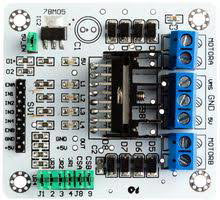
The WPI409 Dual H-Bridge Driver Module, manufactured by Whadda, is a versatile and robust motor driver based on the L298N chip. This module is designed to control DC motors or stepper motors, providing bidirectional control with a high current capacity. It is widely used in robotics, automation, and various DIY electronics projects.

Explore Projects Built with WPI409 dubbele H-brug driver L298N voor DC- of stappenmotor

Use Cirkit Designer to design, explore, and prototype these projects online. Some projects support real-time simulation. Click "Open Project" to start designing instantly!
ESP32-Controlled Dual Stepper Motor Driver System
Image of project carseten: A project utilizing WPI409 dubbele H-brug driver L298N voor DC- of stappenmotor in a practical application
This circuit consists of two L298N DC motor drivers controlled by an ESP32 microcontroller to drive two bipolar stepper motors. The ESP32 uses its GPIO pins to send control signals to the motor drivers, which in turn power the stepper motors with a 12V supply from either a battery or a power supply. The circuit is designed for precise control of stepper motors, likely for applications requiring synchronized movements, such as robotics or CNC machines.
Cirkit Designer LogoOpen Project in Cirkit Designer
Battery-Powered Line Following Robot with L298N Motor Driver and KY-033 Sensors
Image of obstacle-avoiding robot: A project utilizing WPI409 dubbele H-brug driver L298N voor DC- of stappenmotor in a practical application
This circuit is designed to control a two-wheeled robot using an L298N motor driver, powered by two 18650 Li-ion batteries. It includes two KY-033 line tracking sensors for navigation and a 74HC04 inverter to process sensor signals and control the motor driver inputs.
Cirkit Designer LogoOpen Project in Cirkit Designer
ESP32-Controlled Dual DC Motor & Stepper Motor Driver System
Image of Fyp circuit diagram: A project utilizing WPI409 dubbele H-brug driver L298N voor DC- of stappenmotor in a practical application
This circuit controls two DC motors and a stepper motor using an ESP32 microcontroller. The L298N motor driver interfaces with the ESP32 to drive the DC motors, allowing for directional control and speed regulation through PWM. Additionally, the ULN2003A breakout board is used to control the 28BYJ-48 stepper motor, with the ESP32 dictating the stepping sequence. Power is supplied by 9V batteries, with toggle switches to control power flow to the motor drivers.
Cirkit Designer LogoOpen Project in Cirkit Designer
Arduino-Controlled Robotic Vehicle with IR Obstacle Detection and L298N Motor Driver
Image of LFR Car Circuit: A project utilizing WPI409 dubbele H-brug driver L298N voor DC- of stappenmotor in a practical application
This circuit controls two DC gearmotors using an L298N motor driver, which is interfaced with an Arduino Leonardo microcontroller. The Arduino adjusts the speed and direction of the motors through PWM and digital control signals. Power is supplied by a 3xAA battery pack, regulated to the appropriate voltage by an LM2596 step-down module, and an array of IR sensors are connected to the Arduino's analog inputs for potential object detection or line following functionalities.
Cirkit Designer LogoOpen Project in Cirkit Designer

Explore Projects Built with WPI409 dubbele H-brug driver L298N voor DC- of stappenmotor

Use Cirkit Designer to design, explore, and prototype these projects online. Some projects support real-time simulation. Click "Open Project" to start designing instantly!
Image of project carseten: A project utilizing WPI409 dubbele H-brug driver L298N voor DC- of stappenmotor in a practical application
ESP32-Controlled Dual Stepper Motor Driver System
This circuit consists of two L298N DC motor drivers controlled by an ESP32 microcontroller to drive two bipolar stepper motors. The ESP32 uses its GPIO pins to send control signals to the motor drivers, which in turn power the stepper motors with a 12V supply from either a battery or a power supply. The circuit is designed for precise control of stepper motors, likely for applications requiring synchronized movements, such as robotics or CNC machines.
Cirkit Designer LogoOpen Project in Cirkit Designer
Image of obstacle-avoiding robot: A project utilizing WPI409 dubbele H-brug driver L298N voor DC- of stappenmotor in a practical application
Battery-Powered Line Following Robot with L298N Motor Driver and KY-033 Sensors
This circuit is designed to control a two-wheeled robot using an L298N motor driver, powered by two 18650 Li-ion batteries. It includes two KY-033 line tracking sensors for navigation and a 74HC04 inverter to process sensor signals and control the motor driver inputs.
Cirkit Designer LogoOpen Project in Cirkit Designer
Image of Fyp circuit diagram: A project utilizing WPI409 dubbele H-brug driver L298N voor DC- of stappenmotor in a practical application
ESP32-Controlled Dual DC Motor & Stepper Motor Driver System
This circuit controls two DC motors and a stepper motor using an ESP32 microcontroller. The L298N motor driver interfaces with the ESP32 to drive the DC motors, allowing for directional control and speed regulation through PWM. Additionally, the ULN2003A breakout board is used to control the 28BYJ-48 stepper motor, with the ESP32 dictating the stepping sequence. Power is supplied by 9V batteries, with toggle switches to control power flow to the motor drivers.
Cirkit Designer LogoOpen Project in Cirkit Designer
Image of LFR Car Circuit: A project utilizing WPI409 dubbele H-brug driver L298N voor DC- of stappenmotor in a practical application
Arduino-Controlled Robotic Vehicle with IR Obstacle Detection and L298N Motor Driver
This circuit controls two DC gearmotors using an L298N motor driver, which is interfaced with an Arduino Leonardo microcontroller. The Arduino adjusts the speed and direction of the motors through PWM and digital control signals. Power is supplied by a 3xAA battery pack, regulated to the appropriate voltage by an LM2596 step-down module, and an array of IR sensors are connected to the Arduino's analog inputs for potential object detection or line following functionalities.
Cirkit Designer LogoOpen Project in Cirkit Designer

Common Applications and Use Cases

  • Robotics: Controlling the movement of robot wheels or arms.
  • Automation Systems: Driving conveyor belts or automated gates.
  • DIY Projects: Building remote-controlled cars, drones, or other motorized devices.
  • Educational Purposes: Teaching motor control and electronics concepts.

Technical Specifications

Key Technical Details

Parameter Value
Operating Voltage 5V to 35V
Output Current 2A per channel (continuous), 3A peak
Logic Voltage 5V
Control Logic TTL compatible
Power Dissipation 25W (at 75°C)
Dimensions 43mm x 43mm x 27mm
Weight 26g

Pin Configuration and Descriptions

Power and Motor Connections

Pin Name Description
VCC Motor power supply (5V to 35V)
GND Ground
5V Logic power supply (5V)
OUT1 Motor A output 1
OUT2 Motor A output 2
OUT3 Motor B output 1
OUT4 Motor B output 2

Control Pins

Pin Name Description
ENA Enable pin for Motor A (High to enable)
IN1 Control input 1 for Motor A
IN2 Control input 2 for Motor A
ENB Enable pin for Motor B (High to enable)
IN3 Control input 1 for Motor B
IN4 Control input 2 for Motor B

Usage Instructions

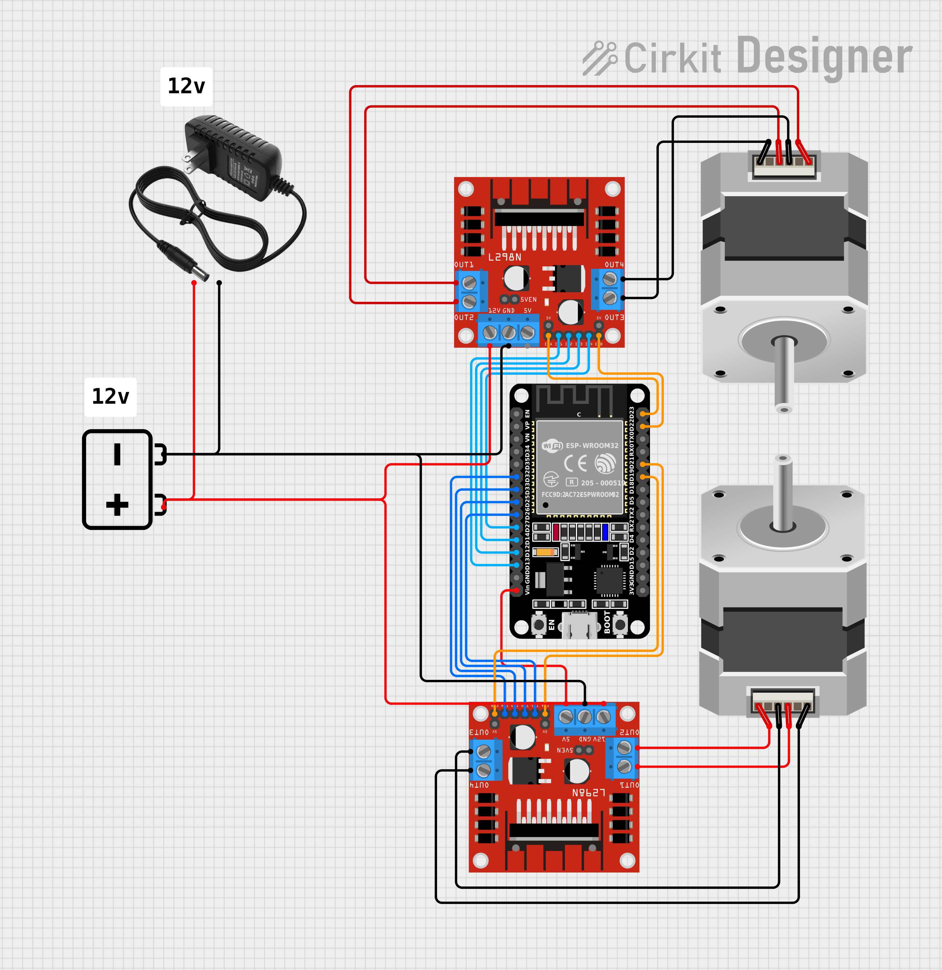
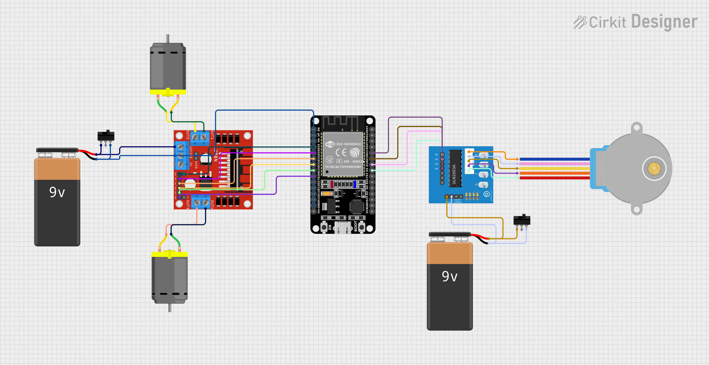
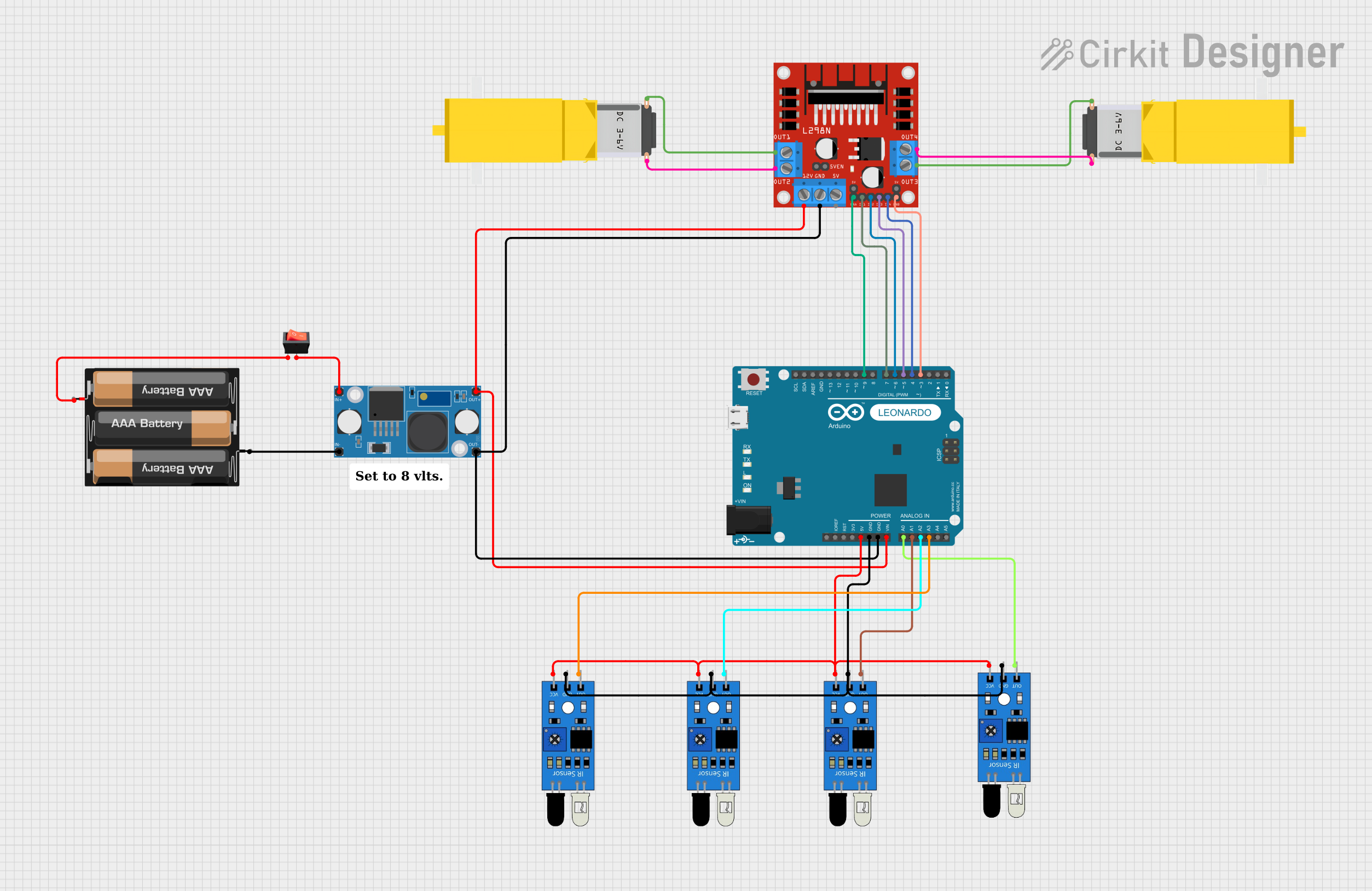
How to Use the Component in a Circuit

  1. Power Connections:

    • Connect the VCC pin to the motor power supply (5V to 35V).
    • Connect the GND pin to the ground of the power supply.
    • Connect the 5V pin to the 5V logic power supply.
  2. Motor Connections:

    • Connect the motor terminals to OUT1 and OUT2 for Motor A.
    • Connect the motor terminals to OUT3 and OUT4 for Motor B.
  3. Control Connections:

    • Connect the ENA pin to a digital output pin on your microcontroller to enable Motor A.
    • Connect the IN1 and IN2 pins to digital output pins on your microcontroller to control the direction of Motor A.
    • Connect the ENB pin to a digital output pin on your microcontroller to enable Motor B.
    • Connect the IN3 and IN4 pins to digital output pins on your microcontroller to control the direction of Motor B.

Important Considerations and Best Practices

  • Heat Dissipation: The L298N chip can get hot during operation. Ensure proper heat dissipation by using a heat sink or cooling fan if necessary.
  • Power Supply: Use a power supply that can provide sufficient current for your motors. Overloading the module can cause damage.
  • Logic Levels: Ensure that the control logic voltage is compatible with your microcontroller (typically 5V).

Example Code for Arduino UNO

// Define motor control pins
const int ENA = 9;
const int IN1 = 8;
const int IN2 = 7;
const int ENB = 3;
const int IN3 = 5;
const int IN4 = 4;

void setup() {
  // Set all the motor control pins as outputs
  pinMode(ENA, OUTPUT);
  pinMode(IN1, OUTPUT);
  pinMode(IN2, OUTPUT);
  pinMode(ENB, OUTPUT);
  pinMode(IN3, OUTPUT);
  pinMode(IN4, OUTPUT);

  // Initialize motors to off
  digitalWrite(ENA, LOW);
  digitalWrite(ENB, LOW);
}

void loop() {
  // Example: Move Motor A forward
  digitalWrite(ENA, HIGH); // Enable Motor A
  digitalWrite(IN1, HIGH); // Set IN1 high
  digitalWrite(IN2, LOW);  // Set IN2 low

  // Example: Move Motor B backward
  digitalWrite(ENB, HIGH); // Enable Motor B
  digitalWrite(IN3, LOW);  // Set IN3 low
  digitalWrite(IN4, HIGH); // Set IN4 high

  delay(2000); // Run motors for 2 seconds

  // Stop motors
  digitalWrite(ENA, LOW);
  digitalWrite(ENB, LOW);

  delay(2000); // Wait for 2 seconds before repeating
}

Troubleshooting and FAQs

Common Issues Users Might Face

  1. Motor Not Running:

    • Solution: Check power connections and ensure the power supply is adequate. Verify that the enable pins (ENA and ENB) are set high.
  2. Motor Running in Wrong Direction:

    • Solution: Check the control pin connections (IN1, IN2, IN3, IN4) and ensure they are set correctly for the desired direction.
  3. Overheating:

    • Solution: Ensure proper heat dissipation with a heat sink or cooling fan. Reduce the load on the motors if necessary.
  4. No Response from Module:

    • Solution: Verify that the logic voltage (5V) is correctly supplied. Check all connections and ensure there are no loose wires.

Solutions and Tips for Troubleshooting

  • Double-Check Connections: Ensure all connections are secure and correctly placed according to the pin configuration.
  • Use a Multimeter: Measure voltages at various points in the circuit to ensure proper power supply and signal levels.
  • Consult Datasheets: Refer to the L298N datasheet for detailed information on the chip's operation and characteristics.

By following this documentation, users can effectively utilize the WPI409 Dual H-Bridge Driver Module for controlling DC or stepper motors in various applications. Whether you are a beginner or an experienced user, this guide provides the necessary information to get started and troubleshoot common issues.