How to Use Mixed Signal Oscilloscope: Examples, Pinouts, and Specs
Introduction
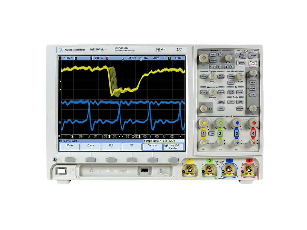
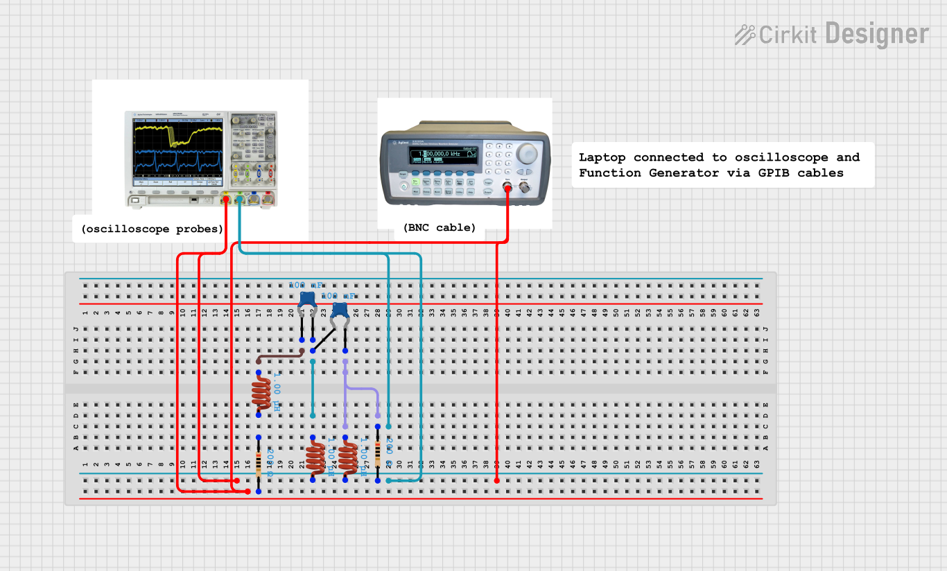
The MSO7034B is a Mixed Signal Oscilloscope from Agilent Technologies that integrates the capabilities of a digital storage oscilloscope (DSO) with a logic analyzer. This powerful tool is designed to capture and display both analog and digital signals, making it an essential instrument for engineers and technicians working on mixed-signal circuits. The MSO7034B is commonly used in applications such as embedded system design, digital design and debugging, power electronics, automotive electronics, and more.
Explore Projects Built with Mixed Signal Oscilloscope
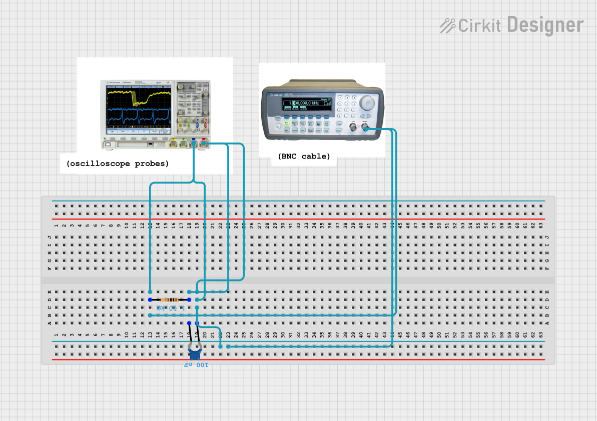
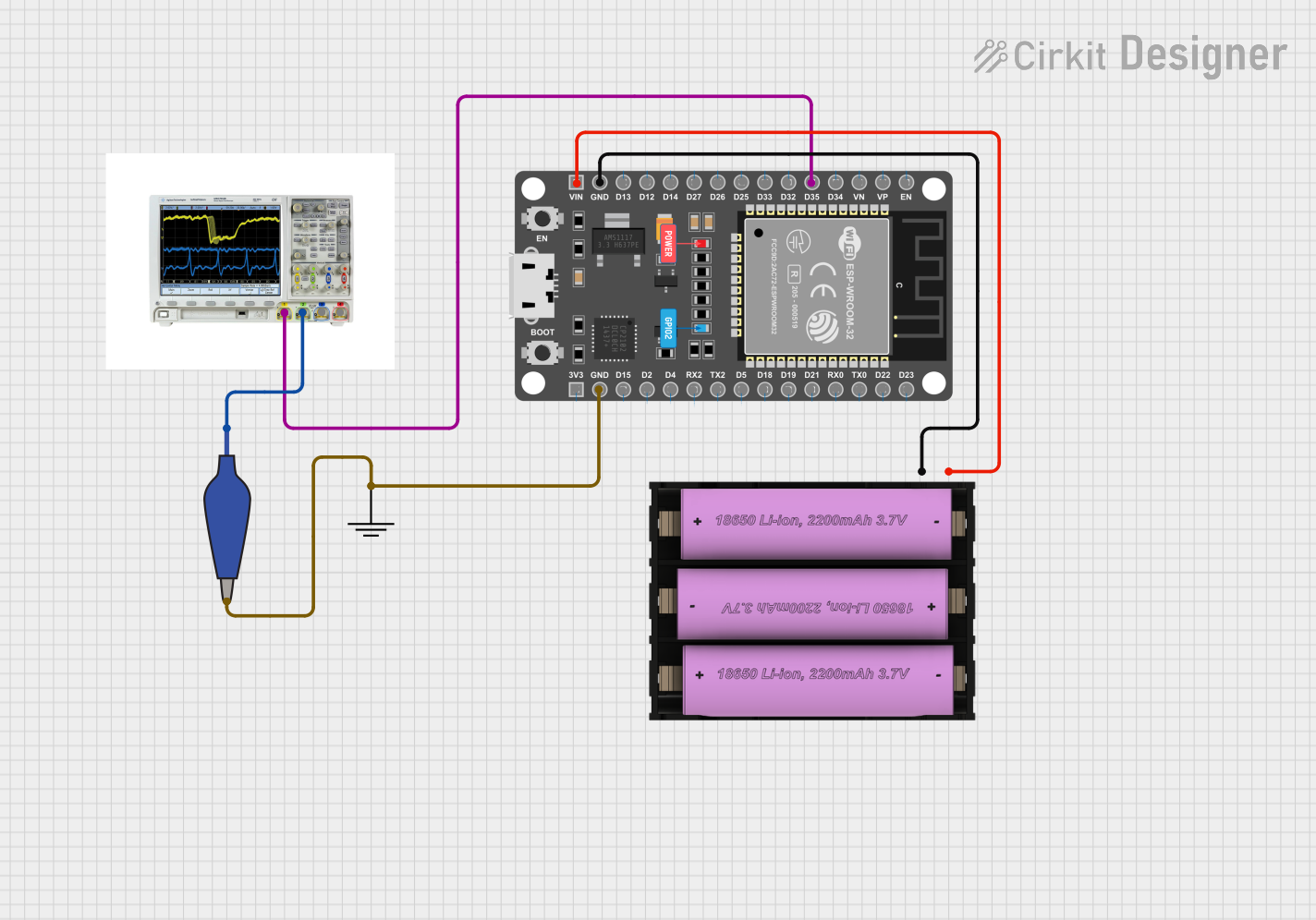
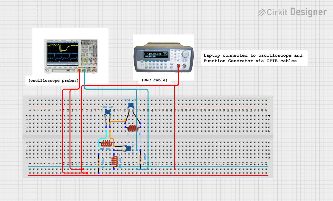
Explore Projects Built with Mixed Signal Oscilloscope
Technical Specifications
Key Technical Details
- Bandwidth: 350 MHz
- Analog Channels: 4
- Digital Channels: 16 (with MSO option)
- Sample Rate: Up to 2 GSa/s (Gigasamples per second)
- Memory Depth: Up to 8 Mpts (Megapoints)
- Display: High-resolution color TFT LCD
- Connectivity: USB, LAN, GPIB (optional)
Pin Configuration and Descriptions
The MSO7034B does not have a traditional "pin configuration" as it is a benchtop instrument. However, it has various connectors and interfaces for connecting to the device under test (DUT) and to other devices or networks.
| Connector/Interface | Description |
|---|---|
| Analog Channel Inputs | BNC connectors for the 4 analog channels |
| Digital Channel Connectors | Connector for the 16 digital channels (requires a logic probe) |
| External Trigger Input | BNC connector for external trigger signal |
| USB Ports | For connecting USB devices, saving data, and system upgrades |
| LAN Port | For network connectivity and remote control |
| GPIB Port (Optional) | For interfacing with GPIB systems |
Usage Instructions
How to Use the MSO7034B in a Circuit
- Powering On: Connect the oscilloscope to a power source and switch it on.
- Connecting to a DUT: Use BNC cables to connect the analog channels to the analog signals of your DUT. For digital signals, connect the logic probe to the digital channel connector and then to the DUT.
- Setting Up the Display: Adjust the vertical and horizontal scales to suit the signals you are measuring. Use the triggering options to stabilize the waveform display.
- Capturing Data: Use the 'Run/Stop' button to start and stop data capture. Utilize the 'Single' button for a one-time capture of the signal.
- Analyzing Signals: Use the built-in measurement tools to analyze signal parameters such as frequency, amplitude, and rise time.
Important Considerations and Best Practices
- Probe Compensation: Always perform probe compensation before taking measurements to ensure accuracy.
- Signal Integrity: Use proper grounding techniques to avoid noise and ensure signal integrity.
- Bandwidth Selection: Select an oscilloscope with a bandwidth that exceeds the highest frequency signal you intend to measure.
- Safety: Be cautious when working with high-voltage signals to avoid damage to the oscilloscope and personal injury.
Troubleshooting and FAQs
Common Issues
- Unstable Waveform Display: Check the trigger settings and ensure that the trigger level is set correctly for the signal.
- Inaccurate Measurements: Confirm that the probes are compensated and that the oscilloscope settings match the signal characteristics.
- No Signal Display: Ensure that the probes are connected correctly and that the oscilloscope is properly configured for the signal type.
Solutions and Tips for Troubleshooting
- Probe Issues: Verify that the probes are functioning correctly and are rated for the signal levels being tested.
- Configuration: Double-check all settings, including time base, vertical sensitivity, and input coupling.
- Firmware Updates: Keep the oscilloscope's firmware up to date to ensure optimal performance and access to the latest features.
FAQs
Q: Can the MSO7034B be used to measure power supply ripple? A: Yes, the MSO7034B can measure power supply ripple using its analog channels.
Q: How can I capture a digital signal burst that occurs infrequently? A: Use the 'Single' capture mode with appropriate trigger settings to capture infrequent events.
Q: Is it possible to save and analyze data on a computer? A: Yes, data can be saved to a USB drive or transferred over LAN for analysis with compatible software.
Q: Can I control the MSO7034B remotely? A: Yes, the MSO7034B supports LAN connectivity for remote control and operation.
For further assistance, consult the Agilent MSO7034B user manual or contact Agilent Technologies support.
(Note: This documentation is a simplified guide and does not cover all aspects of the MSO7034B. Users should refer to the official Agilent MSO7034B manual for comprehensive details and instructions.)