How to Use 3xAAA Battery Pack with Switch and JST: Examples, Pinouts, and Specs
Introduction
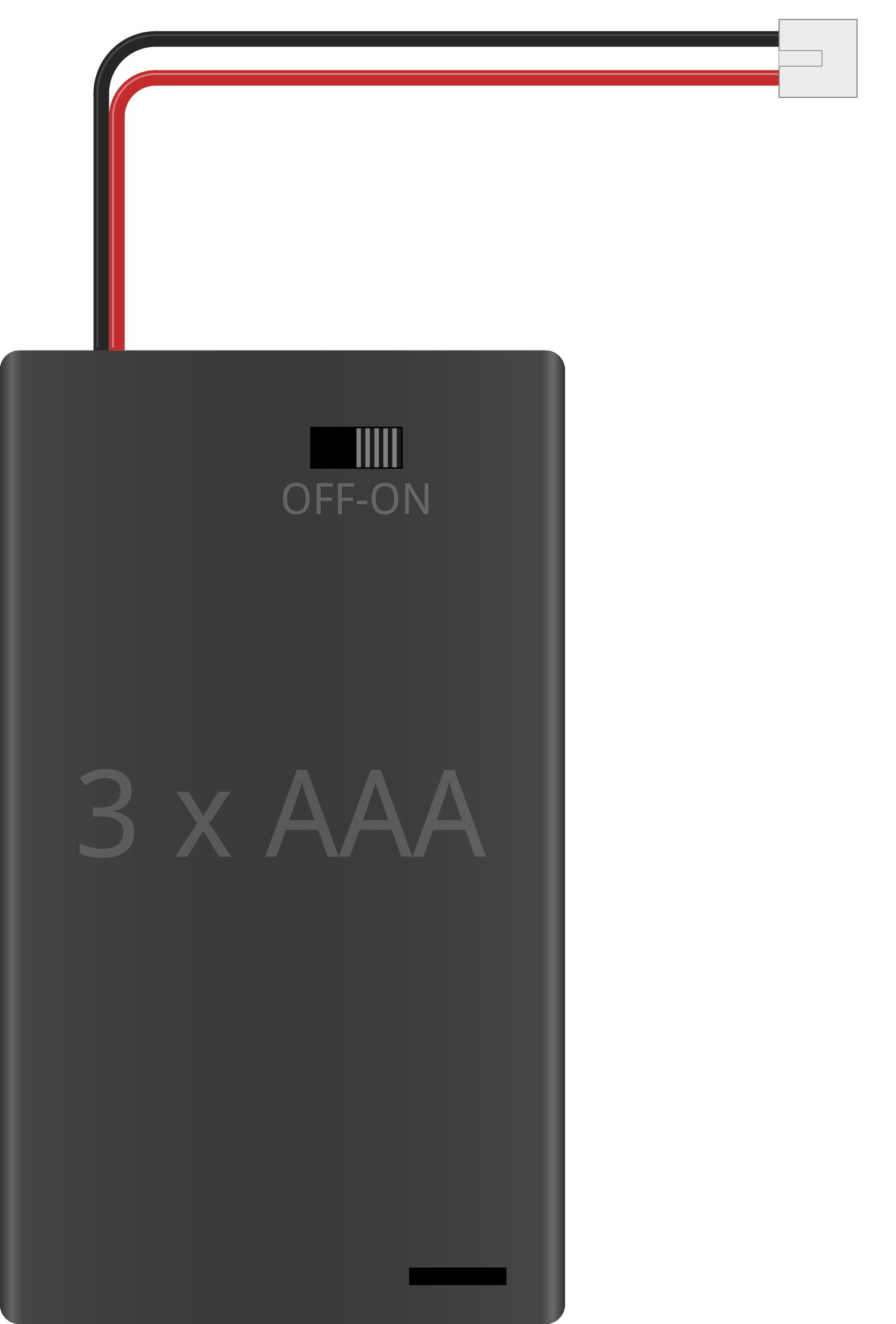
The 3xAAA Battery Pack with Switch and JST Connector is a compact and convenient power solution for portable electronics. This battery holder accommodates three AAA batteries and features an integrated on/off switch and a JST-PH connector for easy connection to a circuit or device. Common applications include powering small microcontroller projects, LED lighting systems, and portable gadgets.
Explore Projects Built with 3xAAA Battery Pack with Switch and JST
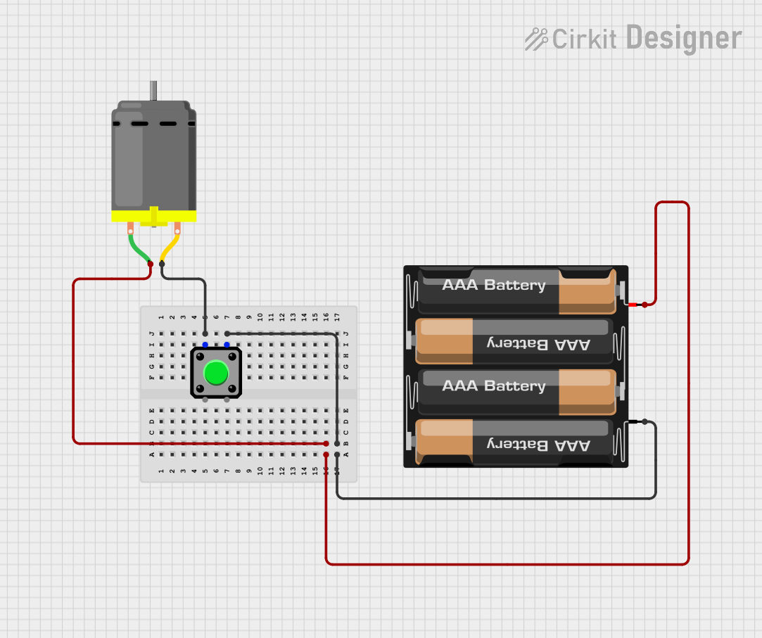
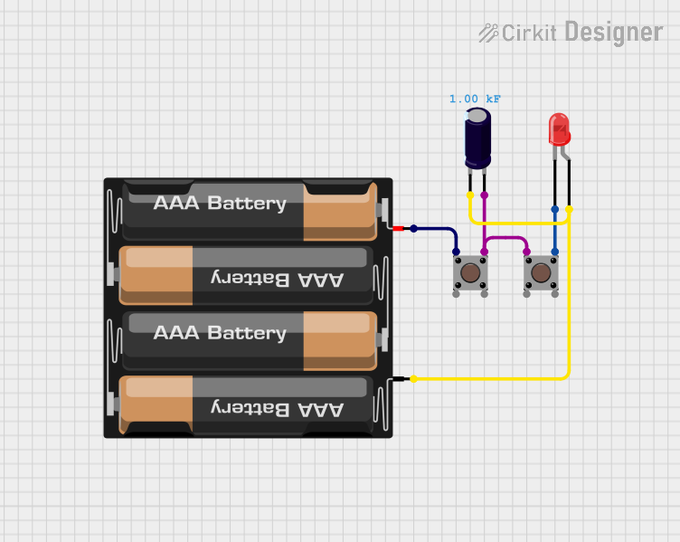

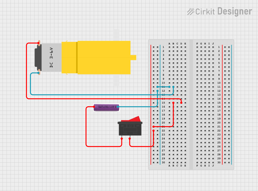
Explore Projects Built with 3xAAA Battery Pack with Switch and JST
Technical Specifications
General Specifications
- Battery Type: AAA
- Number of Batteries: 3
- Nominal Voltage Output: 4.5V (1.5V per AAA battery)
- Maximum Recommended Current: Varies based on the batteries used
- Connector Type: JST-PH 2-pin
- Switch: Slide type, on/off functionality
Pin Configuration and Descriptions
| Pin Number | Description |
|---|---|
| 1 | Positive Voltage (V+) |
| 2 | Ground (GND) |
Usage Instructions
Installing Batteries
- Slide the battery pack's switch to the "OFF" position.
- Open the battery compartment following the indicated direction.
- Insert three AAA batteries ensuring the correct polarity.
- Close the battery compartment securely.
Connecting to a Circuit
- Ensure the battery pack switch is in the "OFF" position before connecting.
- Connect the JST connector to the corresponding JST female connector on your device or circuit board.
- Verify that the polarity matches; red wire to V+ and black wire to GND.
Best Practices
- Always use batteries of the same type, brand, and charge level to prevent imbalances.
- Remove batteries if the pack will not be used for an extended period to avoid leakage.
- Do not exceed the recommended current draw to prevent damage to the batteries or device.
Troubleshooting and FAQs
Common Issues
- Device not powering on: Ensure the switch is in the "ON" position, batteries are properly installed with correct polarity, and that the batteries are charged.
- Intermittent power: Check for loose connections at the JST connector and ensure the battery compartment is securely closed.
FAQs
Q: Can I use rechargeable AAA batteries?
- A: Yes, rechargeable AAA batteries can be used, but ensure they are compatible with the device's voltage requirements.
Q: What is the polarity of the JST connector?
- A: The red wire is positive (V+), and the black wire is negative (GND).
Q: How do I know when to replace the batteries?
- A: Replace the batteries when the device operates erratically or stops functioning, indicating low battery power.
Example Code for Arduino UNO
// This example demonstrates how to read the battery voltage using an Arduino UNO.

int batteryPin = A0; // Analog pin connected to the battery pack's positive terminal

void setup() {
  Serial.begin(9600);
}

void loop() {
  int sensorValue = analogRead(batteryPin); // Read the battery voltage
  float voltage = sensorValue * (5.0 / 1023.0); // Convert to voltage
  Serial.print("Battery Voltage: ");
  Serial.println(voltage);
  delay(1000); // Wait for a second before reading again
}
Note: The above code assumes that the battery pack's positive terminal is connected to an analog pin on the Arduino UNO and that the ground is connected to one of the Arduino's GND pins. The code reads the battery voltage and prints it to the Serial Monitor. Remember to calibrate the voltage reading based on your Arduino's actual reference voltage for accurate results.