How to Use MAX7219 8x8 LED Matrix: Examples, Pinouts, and Specs
Introduction
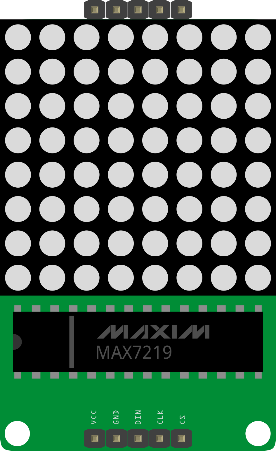
The MAX7219 is a compact, serial input/output common-cathode display driver designed to control up to 64 individual LEDs in an 8x8 matrix configuration. It simplifies the process of driving LED displays by handling multiplexing internally, reducing the need for external components. The MAX7219 communicates via a simple Serial Peripheral Interface (SPI), making it easy to integrate with microcontrollers like the Arduino UNO.
Explore Projects Built with MAX7219 8x8 LED Matrix
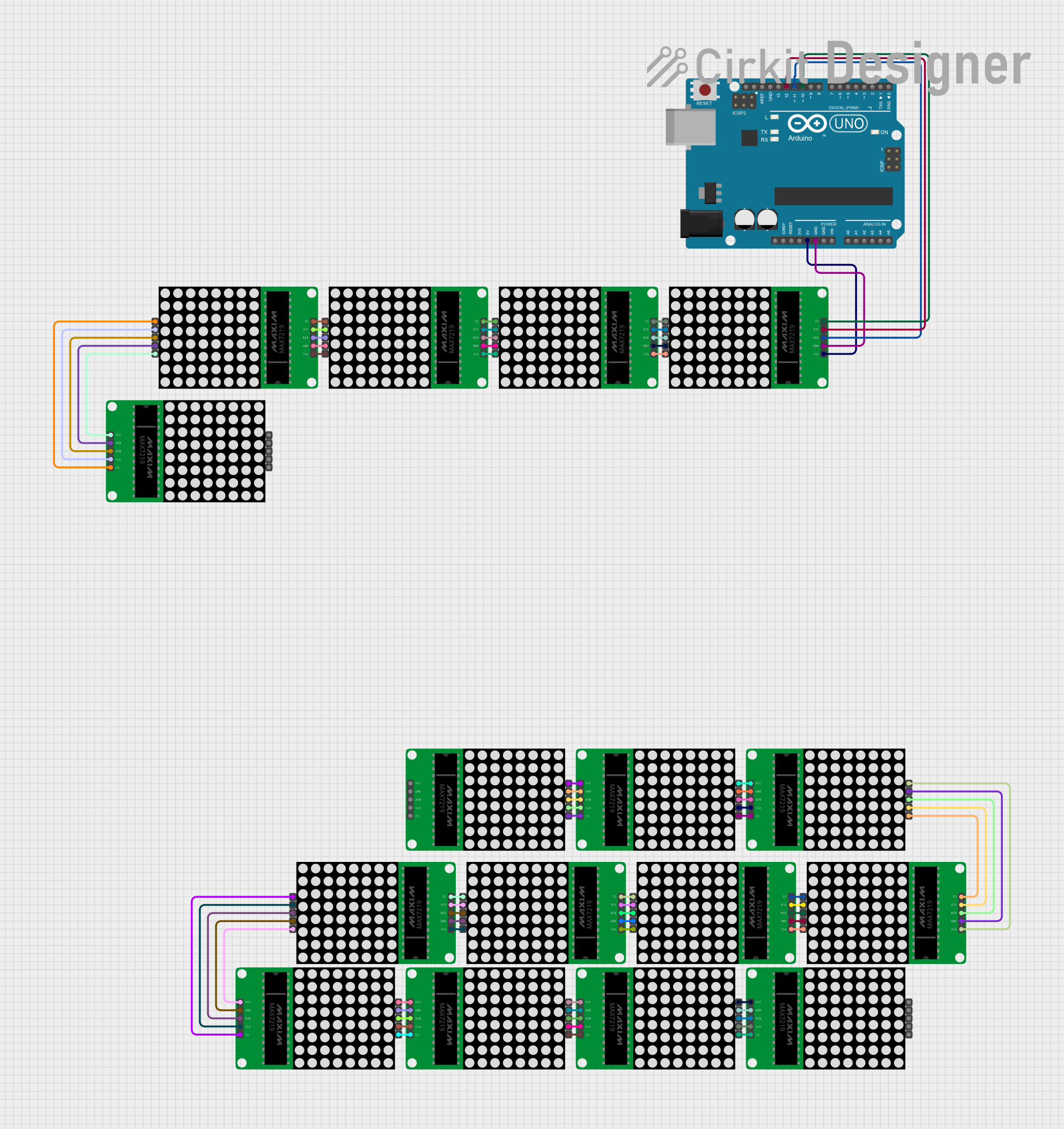

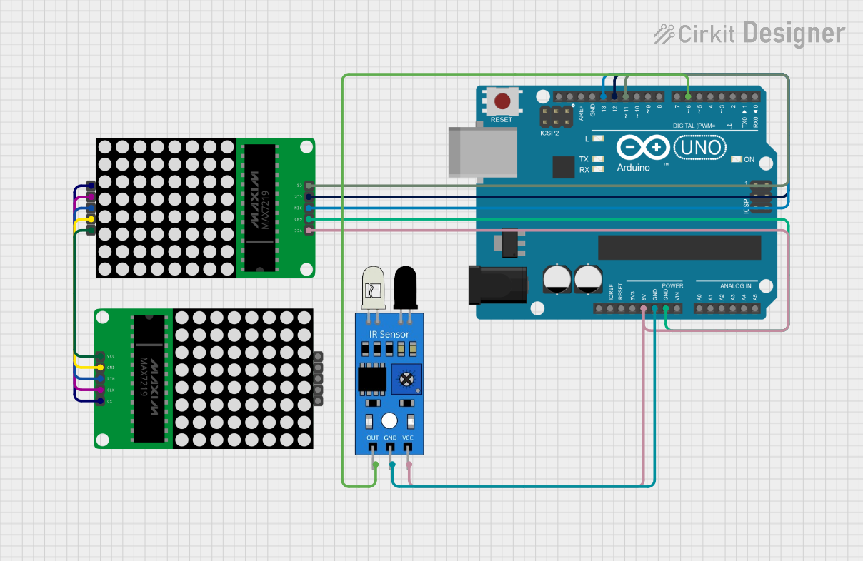
Explore Projects Built with MAX7219 8x8 LED Matrix
Common Applications and Use Cases
- Digital clocks and counters
- Scrolling text displays
- LED signage and message boards
- Gaming devices and scoreboards
- Visual indicators in embedded systems
Technical Specifications
Key Technical Details
- Operating Voltage (Vcc): 4.0V to 5.5V
- Logic Input Voltage: 3.5V (minimum high level), 0.8V (maximum low level)
- Maximum Current per Segment: 40mA
- Maximum Power Dissipation: 500mW
- Communication Protocol: SPI (Serial Peripheral Interface)
- Operating Temperature Range: -40°C to +85°C
- LED Matrix Size: 8x8 (64 LEDs)
- Package Type: 24-pin DIP/SOIC
Pin Configuration and Descriptions
The MAX7219 has 24 pins, which are described in the table below:
| Pin Number | Pin Name | Description |
|---|---|---|
| 1 | DIG 0 | Digit 0 (Row 0 of the LED matrix) |
| 2 | DIG 1 | Digit 1 (Row 1 of the LED matrix) |
| 3 | DIG 2 | Digit 2 (Row 2 of the LED matrix) |
| 4 | DIG 3 | Digit 3 (Row 3 of the LED matrix) |
| 5 | DIG 4 | Digit 4 (Row 4 of the LED matrix) |
| 6 | DIG 5 | Digit 5 (Row 5 of the LED matrix) |
| 7 | DIG 6 | Digit 6 (Row 6 of the LED matrix) |
| 8 | DIG 7 | Digit 7 (Row 7 of the LED matrix) |
| 9 | GND | Ground connection |
| 10 | DOUT | Serial data output (for cascading multiple MAX7219 chips) |
| 11 | LOAD (CS) | Chip select (active low) |
| 12 | CLK | Serial clock input |
| 13 | DIN | Serial data input |
| 14 | V+ | Positive supply voltage |
| 15 | SEG DP | Segment DP (Decimal Point) |
| 16 | SEG G | Segment G |
| 17 | SEG F | Segment F |
| 18 | SEG E | Segment E |
| 19 | SEG D | Segment D |
| 20 | SEG C | Segment C |
| 21 | SEG B | Segment B |
| 22 | SEG A | Segment A |
| 23 | ISET | Current setting resistor (connect to a resistor to set LED current) |
| 24 | V+ | Positive supply voltage |
Usage Instructions
How to Use the MAX7219 in a Circuit
- Power Supply: Connect the V+ pin to a 5V power source and the GND pin to ground.
- LED Matrix Connection: Connect the DIG pins (DIG 0 to DIG 7) to the rows of the LED matrix and the SEG pins (SEG A to SEG DP) to the columns.
- Current Limiting Resistor: Attach a resistor (typically 10kΩ) between the ISET pin and GND to set the LED current.
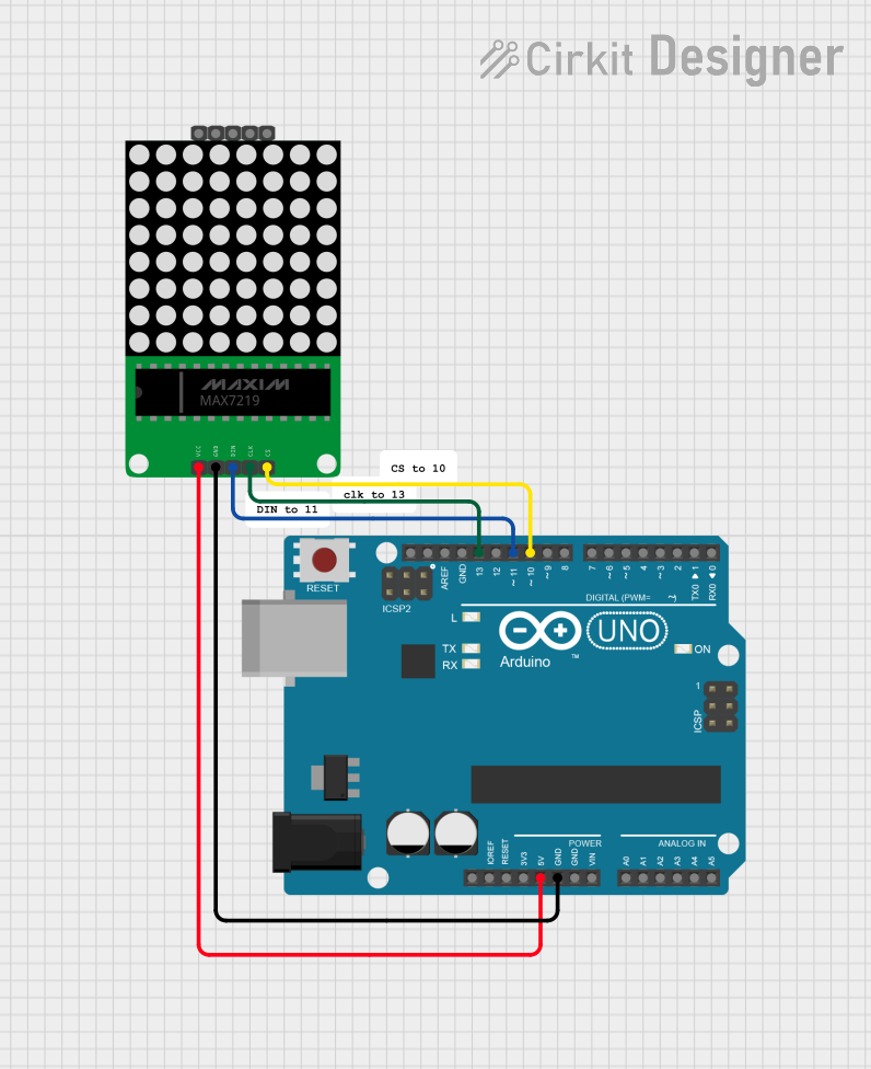
- SPI Communication: Connect the DIN, CLK, and LOAD pins to the microcontroller's SPI pins:
- DIN to MOSI (Master Out Slave In)
- CLK to SCK (Serial Clock)
- LOAD to a digital pin (used as Chip Select)
- Programming: Use an appropriate library (e.g., LedControl for Arduino) to send data to the MAX7219.
Important Considerations and Best Practices
- Cascading Multiple MAX7219 Chips: Connect the DOUT pin of the first MAX7219 to the DIN pin of the next chip. Repeat for additional chips.
- Power Supply: Ensure the power supply can handle the total current draw of all LEDs.
- Bypass Capacitor: Place a 10µF electrolytic capacitor and a 0.1µF ceramic capacitor across the V+ and GND pins to stabilize the power supply.
- Avoid Overdriving LEDs: Use the ISET resistor to limit the current and prevent damage to the LEDs.
Example Code for Arduino UNO
Below is an example of how to control an 8x8 LED matrix using the MAX7219 and the LedControl library:
#include <LedControl.h>

// Initialize LedControl object: DIN pin 12, CLK pin 11, LOAD pin 10, 1 device
LedControl lc = LedControl(12, 11, 10, 1);

void setup() {
  // Wake up the MAX7219 from power-saving mode
  lc.shutdown(0, false);

  // Set brightness level (0 = dim, 15 = brightest)
  lc.setIntensity(0, 8);

  // Clear the display
  lc.clearDisplay(0);

  // Display a pattern (e.g., a diagonal line)
  for (int i = 0; i < 8; i++) {
    lc.setLed(0, i, i, true); // Turn on LED at row i, column i
  }
}

void loop() {
  // No actions in the loop for this example
}
Troubleshooting and FAQs
Common Issues and Solutions
LEDs Not Lighting Up:
- Verify the power supply connections (V+ and GND).
- Check the ISET resistor value (should typically be 10kΩ).
- Ensure the SPI connections (DIN, CLK, LOAD) are correct.
Incorrect or Flickering Display:
- Check for loose or poor connections in the circuit.
- Ensure the SPI clock speed is not too high for the MAX7219.
- Add bypass capacitors (10µF and 0.1µF) across V+ and GND.
Unable to Communicate with the MAX7219:
- Confirm the correct SPI pins are used on the microcontroller.
- Ensure the LOAD pin is properly toggled in the code.
FAQs
Can I cascade multiple MAX7219 chips? Yes, you can cascade multiple MAX7219 chips by connecting the DOUT pin of one chip to the DIN pin of the next. Update the code to address multiple devices.
What is the maximum brightness level? The brightness level can be set from 0 (dim) to 15 (maximum brightness) using the
setIntensity()function.Can I use the MAX7219 with a 3.3V microcontroller? The MAX7219 requires a minimum logic high voltage of 3.5V, so it is not directly compatible with 3.3V systems. Use a level shifter or a 5V microcontroller.
What resistor value should I use for the ISET pin? A 10kΩ resistor is commonly used, but you can adjust the value to control the LED current. Refer to the MAX7219 datasheet for details.
This concludes the documentation for the MAX7219 8x8 LED Matrix.