How to Use Adafruit Analog 2-Axis Joystick: Examples, Pinouts, and Specs
Introduction
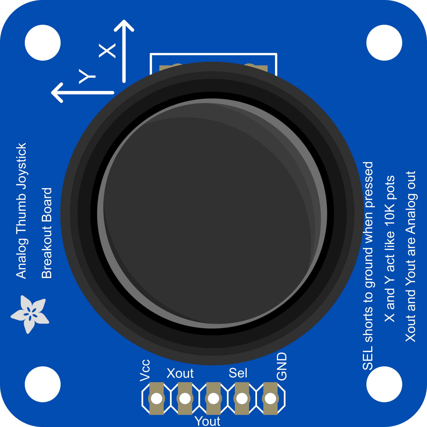
The Adafruit Analog 2-Axis Joystick is a versatile and compact input device that provides a simple interface for user input. It operates using two potentiometers—one for the X-axis and one for the Y-axis—which allow it to measure position or movement along these axes. This joystick is commonly utilized in applications such as gaming consoles, robotics, and various control systems where manual input is required for navigation or operation.
Explore Projects Built with Adafruit Analog 2-Axis Joystick
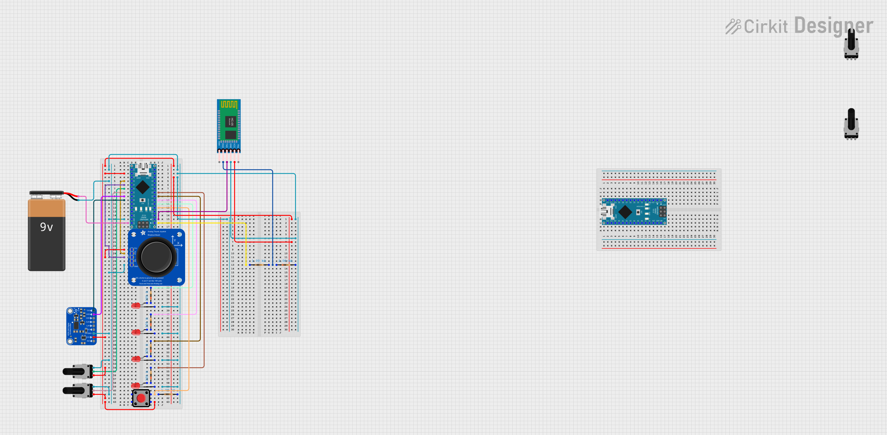
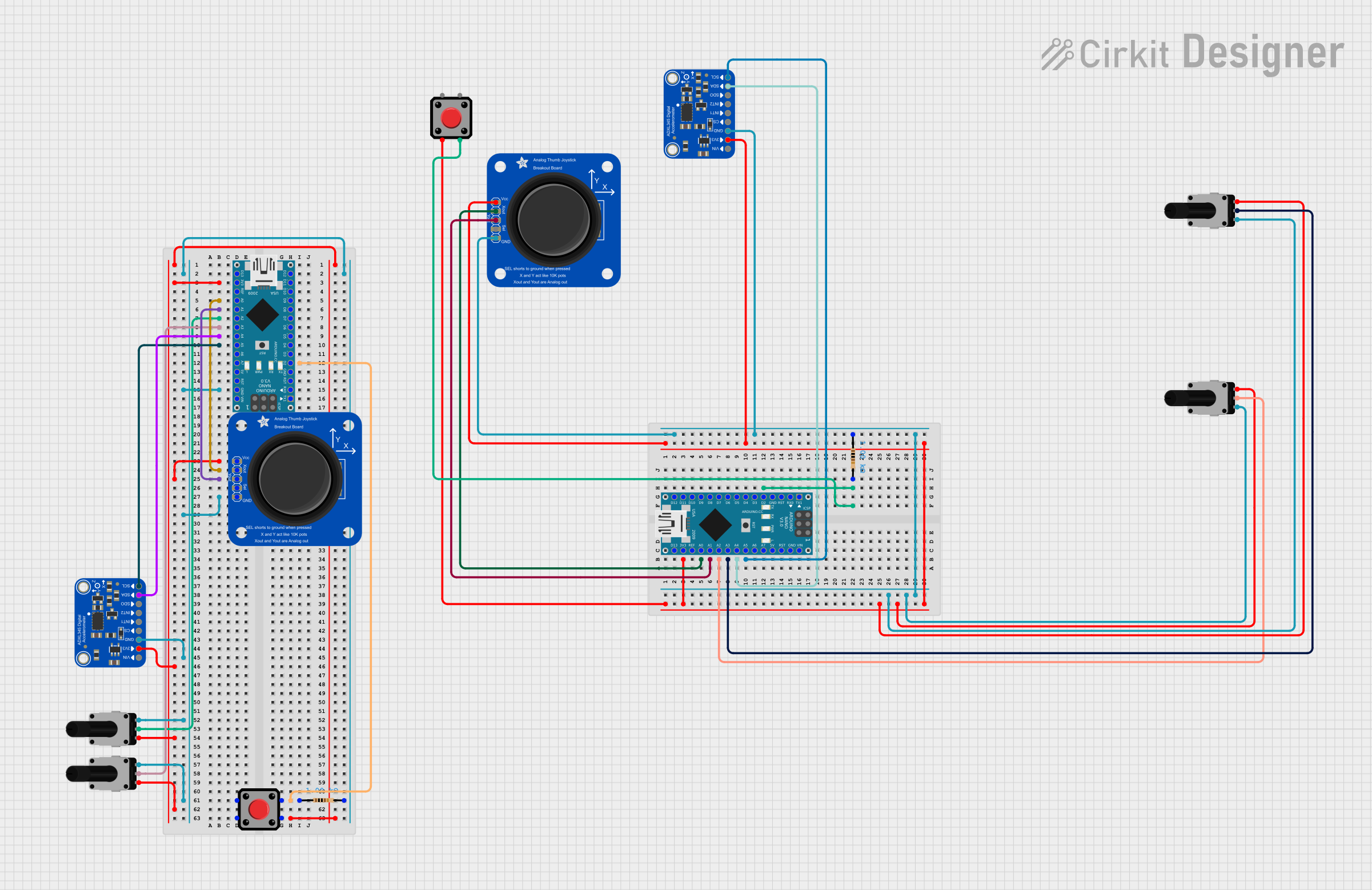
Explore Projects Built with Adafruit Analog 2-Axis Joystick
Technical Specifications
Key Technical Details
- Voltage: 3.3V to 5V
- Current: 10 mA (typical)
- Dimensions: 4 x 2.6 x 3.2 cm (approximate)
- Weight: 15 grams (approximate)
- Potentiometer Resistance: 10k ohms
Pin Configuration and Descriptions
| Pin Number | Name | Description |
|---|---|---|
| 1 | GND | Ground connection |
| 2 | +V | Power supply (3.3V to 5V) |
| 3 | VRx | Voltage output for X-axis |
| 4 | VRy | Voltage output for Y-axis |
| 5 | SW | Switch (activated when joystick is pressed down) |
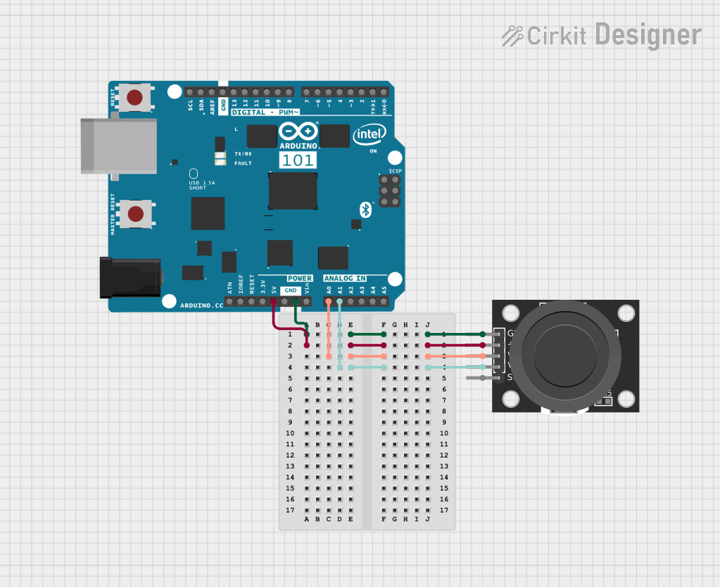
Usage Instructions
How to Use the Component in a Circuit
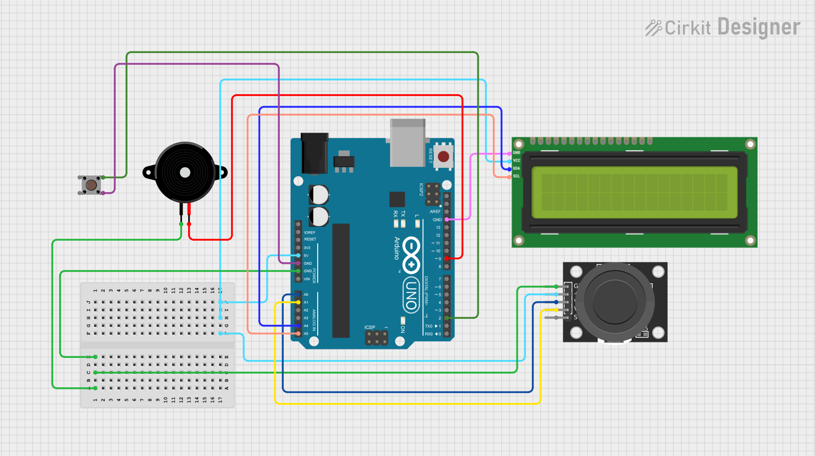
- Power Connections: Connect the +V pin to a 3.3V or 5V power supply and the GND pin to the ground on your circuit.
- Analog Inputs: Connect the VRx and VRy pins to the analog input pins on your microcontroller to read the position of the joystick.
- Digital Input: Connect the SW pin to a digital input pin if you wish to use the built-in switch feature of the joystick.
Important Considerations and Best Practices
- Calibration: When first using the joystick, perform a calibration by reading the center values of the X and Y axes to ensure accurate position readings.
- Debouncing: Implement software debouncing for the switch to avoid false triggering when the joystick is pressed.
- Pull-up Resistor: Use an external or internal pull-up resistor for the switch pin to ensure a stable HIGH signal when the switch is not pressed.
Example Code for Arduino UNO
// Define the analog pins for the joystick
const int xAxisPin = A0;
const int yAxisPin = A1;
const int buttonPin = 2;

void setup() {
  // Initialize the button pin as an input with an internal pull-up resistor
  pinMode(buttonPin, INPUT_PULLUP);
  // Begin serial communication at a baud rate of 9600
  Serial.begin(9600);
}

void loop() {
  // Read the position of the joystick
  int xPosition = analogRead(xAxisPin);
  int yPosition = analogRead(yAxisPin);
  // Read the state of the joystick button
  int buttonState = digitalRead(buttonPin);

  // Print the X and Y positions to the Serial Monitor
  Serial.print("X: ");
  Serial.print(xPosition);
  Serial.print(" | Y: ");
  Serial.print(yPosition);
  Serial.print(" | Button: ");
  Serial.println(buttonState);

  // Add a small delay to prevent flooding the serial output
  delay(100);
}
Troubleshooting and FAQs
Common Issues
- Inaccurate Readings: If the joystick is giving inaccurate readings, ensure that it is properly calibrated and that the power supply is stable.
- Button Not Responding: If the button is not responding, check the connection and ensure that the pull-up resistor is correctly configured.
Solutions and Tips for Troubleshooting
- Calibration: To calibrate the joystick, read the center values of the X and Y axes when the joystick is at rest and use these values as a reference point.
- Stable Power Supply: Ensure that the power supply is within the specified range and is not fluctuating.
- Check Connections: Verify that all connections are secure and that there are no loose wires or cold solder joints.
FAQs
Q: Can I use this joystick with a 3.3V system? A: Yes, the Adafruit Analog 2-Axis Joystick can operate with a 3.3V power supply.
Q: How do I know if the joystick is centered? A: The joystick is centered when the analog output values for both the X and Y axes are approximately half of the maximum analog reading value.
Q: What is the function of the SW pin? A: The SW pin is connected to a switch that is activated when the joystick is pressed down. It can be used as a digital input to detect this action.