How to Use 3.5mm Jack: Examples, Pinouts, and Specs
Introduction
The 3.5mm jack, also known as a headphone jack or TRS connector, is a widely used audio connector designed for transmitting analog audio signals. It is commonly found in headphones, smartphones, audio players, and other audio devices. The 3.5mm jack is versatile and supports mono, stereo, and even microphone connections depending on its configuration.
Explore Projects Built with 3.5mm Jack

Explore Projects Built with 3.5mm Jack
Common Applications and Use Cases
- Connecting headphones or earphones to audio devices
- Transmitting audio signals between devices (e.g., from a smartphone to a speaker)
- Integrating microphones for audio input
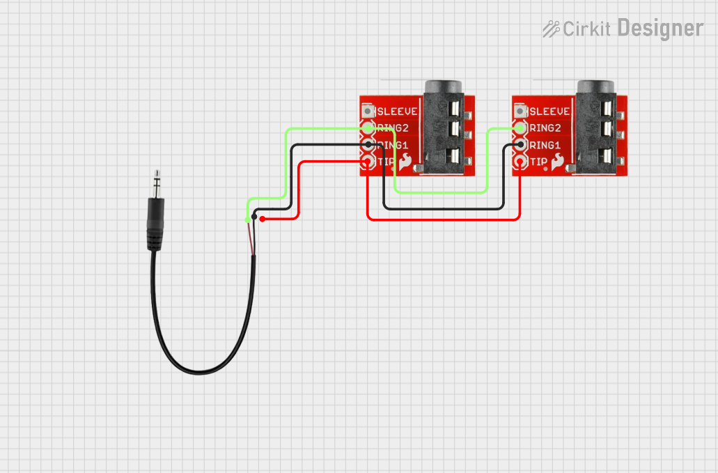
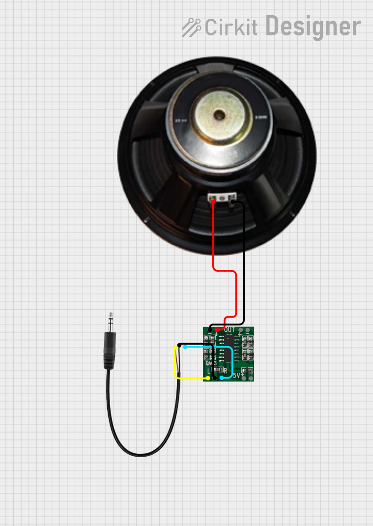
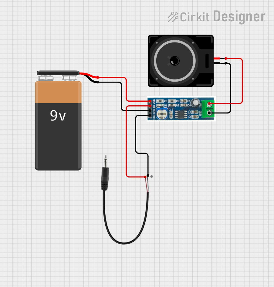
- Used in DIY audio projects and custom audio circuits
Technical Specifications
The 3.5mm jack comes in various configurations, such as TS (Tip-Sleeve), TRS (Tip-Ring-Sleeve), and TRRS (Tip-Ring-Ring-Sleeve). Each configuration supports different functionalities, such as mono audio, stereo audio, or stereo with microphone support.
General Specifications
- Connector Type: 3.5mm audio jack
- Supported Configurations: TS, TRS, TRRS
- Signal Type: Analog audio
- Voltage Range: Typically 0.5V to 2V (line-level audio signals)
- Current Rating: Typically less than 10mA
- Material: Gold-plated or nickel-plated contacts for durability and conductivity
Pin Configuration and Descriptions
TRS (Tip-Ring-Sleeve) Configuration
| Pin Name | Description | Signal Type |
|---|---|---|
| Tip | Left audio channel | Analog audio |
| Ring | Right audio channel | Analog audio |
| Sleeve | Ground (common return path) | Ground connection |
TRRS (Tip-Ring-Ring-Sleeve) Configuration
| Pin Name | Description | Signal Type |
|---|---|---|
| Tip | Left audio channel | Analog audio |
| Ring 1 | Right audio channel | Analog audio |
| Ring 2 | Microphone input or ground | Analog audio/Ground |
| Sleeve | Ground (common return path) | Ground connection |
Note: The exact pinout for TRRS jacks may vary depending on the standard used (e.g., CTIA or OMTP). Always verify the pinout for your specific application.
Usage Instructions
How to Use the 3.5mm Jack in a Circuit
- Identify the Configuration: Determine whether your application requires a TS, TRS, or TRRS jack based on the number of audio channels and whether a microphone is needed.
- Connect the Pins:
- For TRS: Connect the tip to the left audio channel, the ring to the right audio channel, and the sleeve to ground.
- For TRRS: Follow the specific pinout for your device (e.g., CTIA or OMTP standard).
- Soldering: If using a panel-mount jack, solder the appropriate wires to the jack's terminals. Use heat shrink tubing to insulate the connections.
- Mounting: Secure the jack in your device's enclosure using the provided nut or mounting hardware.
Important Considerations and Best Practices
- Avoid Short Circuits: Ensure that the soldered connections do not touch each other to prevent short circuits.
- Use Shielded Cables: For longer audio connections, use shielded cables to minimize noise and interference.
- Verify Standards: When using TRRS jacks, confirm whether your device follows the CTIA or OMTP standard to ensure compatibility.
- Test Connections: Use a multimeter to verify continuity and proper connections before powering the circuit.
Example: Connecting a 3.5mm Jack to an Arduino UNO
The 3.5mm jack can be used to input audio signals into an Arduino for processing. Below is an example of how to connect a TRS jack to an Arduino for basic audio signal reading.
Circuit Diagram
- Tip: Connect to Arduino analog input pin (e.g., A0).
- Sleeve: Connect to Arduino GND.
- Ring: Leave unconnected (for mono input).
Arduino Code Example
// Simple Arduino code to read audio signal from a 3.5mm jack
// connected to analog pin A0 and print the values to the Serial Monitor.

const int audioPin = A0; // Analog pin connected to the 3.5mm jack's tip

void setup() {
  Serial.begin(9600); // Initialize serial communication at 9600 baud
}

void loop() {
  int audioValue = analogRead(audioPin); // Read the audio signal
  Serial.println(audioValue); // Print the signal value to the Serial Monitor
  delay(10); // Small delay to avoid overwhelming the Serial Monitor
}
Note: The Arduino's analog input can only read DC signals. To process AC audio signals, you may need to add a DC bias circuit.
Troubleshooting and FAQs
Common Issues
No Audio Output or Input:
- Cause: Incorrect wiring or soldering.
- Solution: Double-check the pin connections and ensure proper soldering.
Static or Noise in Audio:
- Cause: Poor shielding or loose connections.
- Solution: Use shielded cables and ensure all connections are secure.
Incompatible TRRS Standard:
- Cause: Mismatch between CTIA and OMTP standards.
- Solution: Use an adapter or rewire the connections to match the required standard.
Low Audio Signal:
- Cause: Weak source signal or improper connection.
- Solution: Verify the source device's output level and check the connections.
FAQs
Q1: Can I use a 3.5mm jack for digital audio signals?
A1: No, the 3.5mm jack is designed for analog audio signals. For digital audio, consider using connectors like TOSLINK or HDMI.
Q2: How do I identify the pinout of a 3.5mm jack?
A2: Use a multimeter to test continuity between the jack's terminals and the corresponding sections (tip, ring, sleeve).
Q3: Can I use a TRRS jack for stereo audio only?
A3: Yes, you can leave the microphone pin (Ring 2) unconnected and use the Tip, Ring 1, and Sleeve for stereo audio.
Q4: What is the difference between CTIA and OMTP standards?
A4: The CTIA standard uses the second ring for the microphone and the sleeve for ground, while OMTP swaps these connections. Always verify the standard used by your device.