How to Use TP5100: Examples, Pinouts, and Specs
Introduction
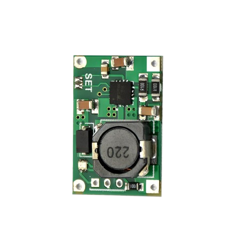
The TP5100 from Electronics Hut is a versatile and efficient charging and protection module designed for lithium batteries. It is capable of handling both single-cell and dual-cell configurations, providing a convenient solution for a wide range of applications including portable devices, power banks, and DIY electronics projects.
Explore Projects Built with TP5100


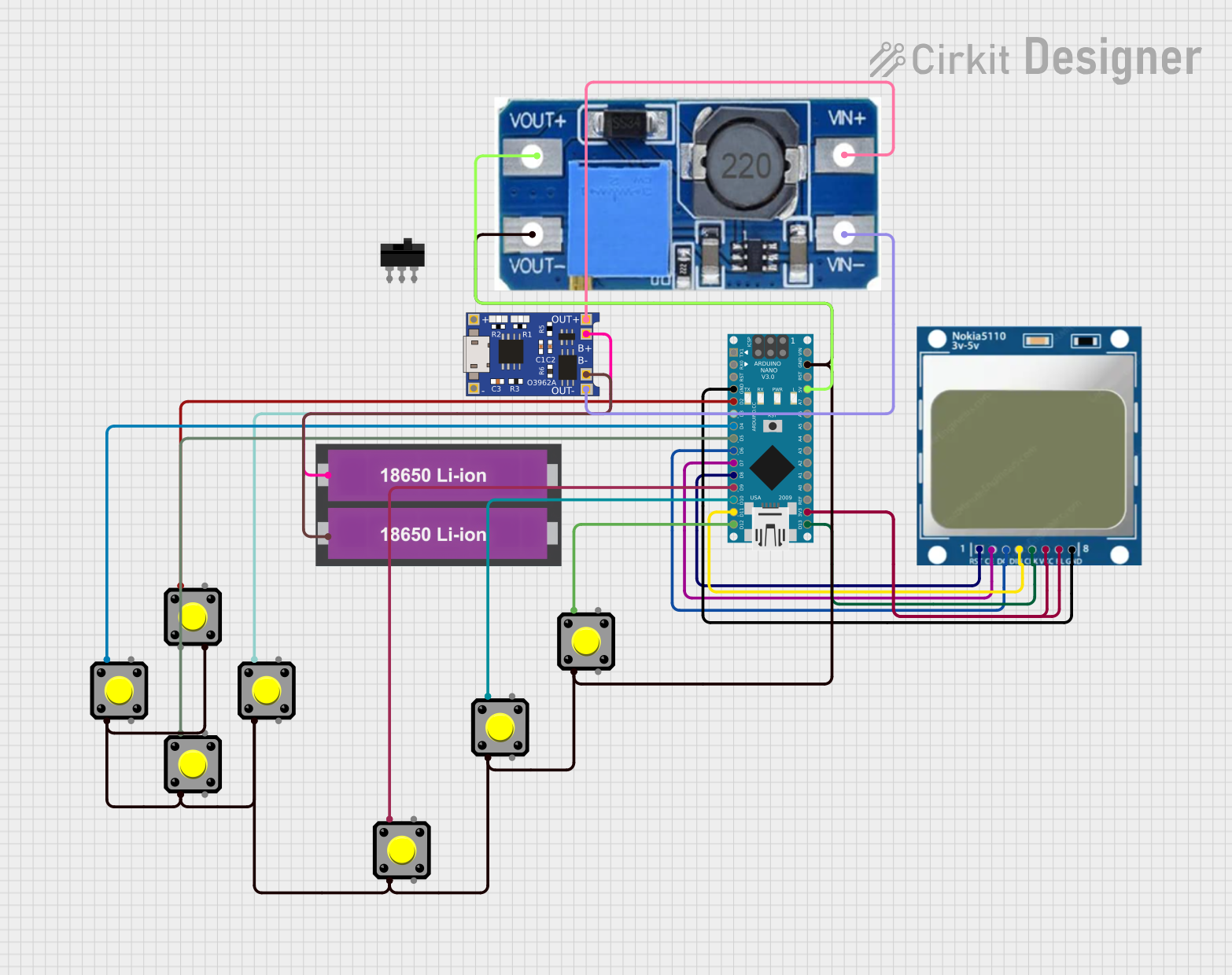
Explore Projects Built with TP5100
Common Applications and Use Cases
- Portable electronic devices
- DIY power banks
- Rechargeable battery packs
- Solar-powered systems
- IoT devices requiring battery management
Technical Specifications
Key Technical Details
- Input Voltage: 5V-18V
- Charging Current: Programmable, up to 2A
- Battery Configuration: Supports single-cell (4.2V) and dual-cell (8.4V) lithium batteries
- Charging Accuracy: ±1.5%
- Operating Temperature Range: -20°C to 85°C
Pin Configuration and Descriptions
| Pin Number | Pin Name | Description |
|---|---|---|
| 1 | BAT+ | Battery positive terminal |
| 2 | BAT- | Battery negative terminal |
| 3 | VCC | Input power supply positive terminal |
| 4 | GND | Input power supply ground terminal |
| 5 | CHG | Charging status output (active low) |
| 6 | STDBY | Standby status output (active low) |
Usage Instructions
How to Use the TP5100 in a Circuit
- Power Supply Connection: Connect a 5V-18V power supply to the VCC and GND pins.
- Battery Connection: Attach the positive terminal of the lithium battery to the BAT+ pin and the negative terminal to the BAT- pin.
- Status Indicators: Connect LEDs or other indicators to the CHG and STDBY pins to monitor the charging and standby status.
Important Considerations and Best Practices
- Ensure the input voltage does not exceed 18V to prevent damage to the module.
- Set the charging current according to the battery's specifications to avoid overcharging.
- Use a multimeter to verify connections and voltages before powering the module.
- Avoid exposing the module to temperatures outside the specified operating range.
Troubleshooting and FAQs
Common Issues
- LED Indicator Not Lighting Up: Check the power supply connections and ensure the input voltage is within the specified range.
- Battery Not Charging: Verify that the battery connections are secure and the battery is not defective.
- Module Overheating: Reduce the charging current if the module becomes too hot during operation.
Solutions and Tips for Troubleshooting
- Double-check all connections for proper polarity and secure fit.
- Use a heat sink if the module is consistently running hot.
- If the battery is not charging, try a different power supply or battery to isolate the issue.
FAQs
Q: Can the TP5100 charge other types of batteries? A: The TP5100 is specifically designed for lithium batteries and should not be used with other battery chemistries.
Q: Is it possible to adjust the charging current? A: Yes, the charging current can be programmed via external resistors. Refer to the datasheet for the appropriate resistor values.
Q: What does it mean when both the CHG and STDBY LEDs are off? A: This typically indicates that the battery is fully charged and the module has entered standby mode.
Example Code for Arduino UNO
// Define TP5100 status pins
const int CHG_PIN = 7;   // TP5100 CHG pin connected to Arduino pin 7
const int STDBY_PIN = 8; // TP5100 STDBY pin connected to Arduino pin 8

void setup() {
  pinMode(CHG_PIN, INPUT);
  pinMode(STDBY_PIN, INPUT);
  Serial.begin(9600);
}

void loop() {
  // Read the charging and standby status
  bool isCharging = !digitalRead(CHG_PIN);
  bool isStandby = !digitalRead(STDBY_PIN);

  // Output the status to the serial monitor
  if (isCharging) {
    Serial.println("Battery is charging...");
  } else if (isStandby) {
    Serial.println("Battery is fully charged and in standby mode.");
  } else {
    Serial.println("Battery is not charging.");
  }

  // Wait for a second before reading the status again
  delay(1000);
}
This example code for the Arduino UNO reads the charging and standby status from the TP5100 module and outputs the information to the serial monitor. Make sure to connect the CHG and STDBY pins of the TP5100 to the corresponding pins on the Arduino UNO as defined in the code.