How to Use 4S BMS: Examples, Pinouts, and Specs
Introduction
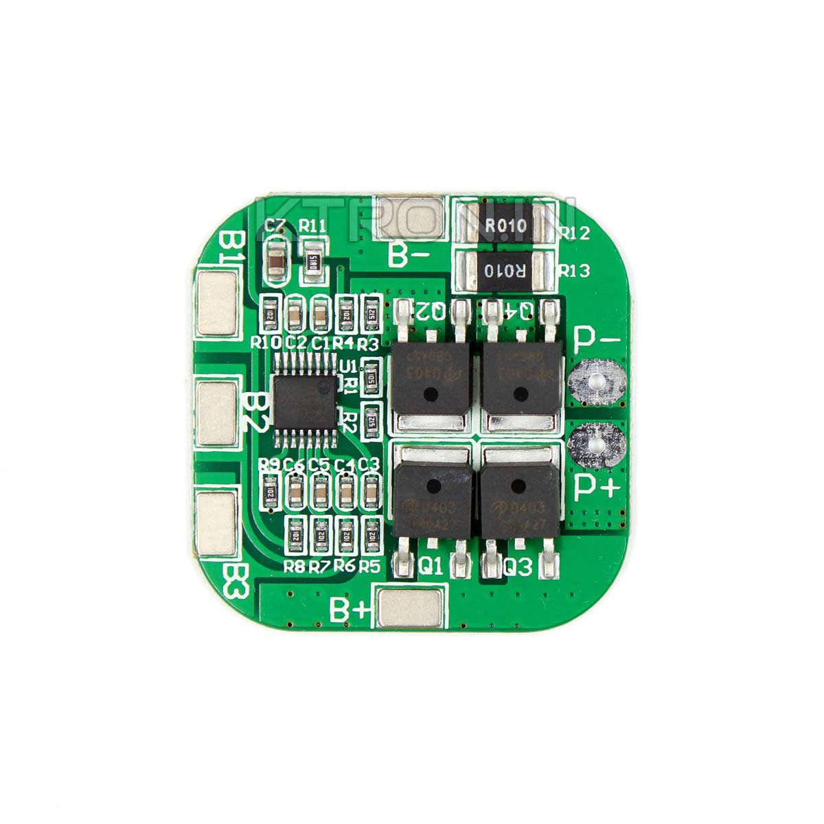
A 4S Battery Management System (BMS) is a crucial component for managing and monitoring the charging and discharging processes of a 4-cell lithium battery pack. It ensures the safety of the battery pack by preventing overcharging, over-discharging, and short circuits, thereby extending the battery's lifespan. Common applications of a 4S BMS include electric vehicles, renewable energy storage systems, portable electronics, and any other devices that utilize a 4-cell lithium battery pack.
Explore Projects Built with 4S BMS


Explore Projects Built with 4S BMS
Technical Specifications
Key Technical Details
| Parameter | Value |
|---|---|
| Battery Configuration | 4S (4 cells in series) |
| Nominal Voltage | 14.8V (3.7V per cell) |
| Maximum Charging Voltage | 16.8V (4.2V per cell) |
| Overcharge Protection | 4.25V ± 0.05V per cell |
| Over-discharge Protection | 2.5V ± 0.1V per cell |
| Maximum Continuous Current | 30A |
| Balance Current | 60mA |
| Operating Temperature | -40°C to 85°C |
Pin Configuration and Descriptions
| Pin Number | Pin Name | Description |
|---|---|---|
| 1 | B- | Battery negative terminal |
| 2 | B1 | Connection to the positive terminal of cell 1 |
| 3 | B2 | Connection to the positive terminal of cell 2 |
| 4 | B3 | Connection to the positive terminal of cell 3 |
| 5 | B4 | Connection to the positive terminal of cell 4 |
| 6 | P- | Power output negative terminal |
| 7 | P+ | Power output positive terminal |
Usage Instructions
How to Use the Component in a Circuit
Connect the Battery Pack:
- Connect the negative terminal of the battery pack to the B- pin.
- Connect the positive terminal of cell 1 to the B1 pin.
- Connect the positive terminal of cell 2 to the B2 pin.
- Connect the positive terminal of cell 3 to the B3 pin.
- Connect the positive terminal of cell 4 to the B4 pin.
Connect the Load/Charger:
- Connect the negative terminal of the load/charger to the P- pin.
- Connect the positive terminal of the load/charger to the P+ pin.
Important Considerations and Best Practices
- Ensure Proper Connections: Double-check all connections to ensure they are correct and secure. Incorrect connections can damage the BMS and the battery pack.
- Use Appropriate Wire Gauges: Use wires that can handle the maximum continuous current rating of the BMS to prevent overheating and potential hazards.
- Monitor Temperature: Ensure the BMS operates within the specified temperature range to avoid malfunction or damage.
- Balance Charging: Regularly balance charge the battery pack to maintain the health and performance of each cell.
Troubleshooting and FAQs
Common Issues Users Might Face
BMS Not Powering On:
- Solution: Check all connections to ensure they are secure and correct. Verify that the battery pack is charged.
Overcharge/Over-discharge Protection Triggering Frequently:
- Solution: Ensure the battery pack is within the specified voltage range. Replace any faulty cells that may be causing the issue.
Uneven Cell Voltages:
- Solution: Perform a balance charge to equalize the voltages of all cells. If the issue persists, check for faulty cells.
FAQs
Q1: Can I use a 4S BMS with a different battery configuration?
- A1: No, a 4S BMS is specifically designed for a 4-cell series configuration. Using it with a different configuration can result in improper operation and potential damage.
Q2: How do I know if the BMS is balancing the cells?
- A2: Most BMS units have indicator LEDs or other signals to show when balancing is occurring. Refer to the specific BMS model's datasheet for details.
Q3: Can I connect multiple 4S BMS units in parallel?
- A3: It is not recommended to connect multiple BMS units in parallel as it can lead to improper balancing and protection issues.
Example Code for Arduino UNO
If you are using the 4S BMS with an Arduino UNO for monitoring purposes, you can use the following example code to read the voltage of each cell:
// Example code to read cell voltages using Arduino UNO
// Connect the BMS cell outputs to the analog pins of the Arduino

const int cell1Pin = A0; // Pin connected to B1
const int cell2Pin = A1; // Pin connected to B2
const int cell3Pin = A2; // Pin connected to B3
const int cell4Pin = A3; // Pin connected to B4

void setup() {
  Serial.begin(9600); // Initialize serial communication
}

void loop() {
  float cell1Voltage = analogRead(cell1Pin) * (5.0 / 1023.0) * 4.2;
  float cell2Voltage = analogRead(cell2Pin) * (5.0 / 1023.0) * 4.2;
  float cell3Voltage = analogRead(cell3Pin) * (5.0 / 1023.0) * 4.2;
  float cell4Voltage = analogRead(cell4Pin) * (5.0 / 1023.0) * 4.2;

  Serial.print("Cell 1 Voltage: ");
  Serial.println(cell1Voltage);
  Serial.print("Cell 2 Voltage: ");
  Serial.println(cell2Voltage);
  Serial.print("Cell 3 Voltage: ");
  Serial.println(cell3Voltage);
  Serial.print("Cell 4 Voltage: ");
  Serial.println(cell4Voltage);

  delay(1000); // Wait for 1 second before the next reading
}
This code reads the voltage of each cell connected to the analog pins of the Arduino UNO and prints the values to the serial monitor. Ensure that the voltage divider is used if the cell voltage exceeds the Arduino's analog input range.
This documentation provides a comprehensive guide to understanding, using, and troubleshooting a 4S Battery Management System (BMS). Whether you are a beginner or an experienced user, this guide aims to help you effectively manage your 4-cell lithium battery pack.