Cirkit Designer Logo
Cirkit Designer
Your all-in-one circuit design IDE
Home / 
Component Documentation

How to Use TCA 9548A: Examples, Pinouts, and Specs

Image of TCA 9548A
Cirkit Designer LogoDesign with TCA 9548A in Cirkit Designer

Introduction

The TCA9548A is an I2C multiplexer that allows a single I2C master device to communicate with multiple I2C devices across up to eight independent I2C buses (channels). This component is particularly useful in applications where multiple I2C devices with the same address need to coexist on the same system. By isolating each device on a separate channel, the TCA9548A eliminates address conflicts and simplifies system design.

Explore Projects Built with TCA 9548A

Use Cirkit Designer to design, explore, and prototype these projects online. Some projects support real-time simulation. Click "Open Project" to start designing instantly!
ESP32-Based I2C Multiplexer Interface
Image of 8 light sensors: A project utilizing TCA 9548A in a practical application
This circuit utilizes an ESP32 microcontroller to interface with multiple I2C devices through an Adafruit TCA9548A I2C multiplexer. The ESP32 communicates with the TCA9548A via I2C, and the multiplexer allows for up to eight separate I2C buses, each connected to a 5-pin relimate connector. This setup enables the ESP32 to manage multiple I2C devices that may share the same address, by selecting which bus is active at any given time.
Cirkit Designer LogoOpen Project in Cirkit Designer
ESP32-CAM and T-Display-S3 Based Obstacle-Avoiding Robot
Image of EyeBot: A project utilizing TCA 9548A in a practical application
This circuit features an ESP32-CAM module and a T-Display-S3 for user interface, connected to a motor driver controlling two hobby gearmotors. An infrared proximity sensor provides input to the system, likely for obstacle detection or distance measurement. The electrolytic capacitor is used for power supply stabilization, ensuring smooth operation of the motor driver and connected motors.
Cirkit Designer LogoOpen Project in Cirkit Designer
ESP32-Based I2C Communication Hub with Multiplexer and Expander
Image of Lights: A project utilizing TCA 9548A in a practical application
This circuit features an Olimex ESP32-EVB microcontroller unit (MCU) for processing and connectivity, interfaced with an MCP23017 I/O expander and an Adafruit TCA9548A I2C multiplexer to expand the number of I/O lines and allow multiple I2C devices to communicate with the MCU over the same bus. Pull-up resistors are connected to the I2C lines for proper bus operation, and both the MCP23017 and TCA9548A have their reset lines pulled high, likely for normal operation without external reset control.
Cirkit Designer LogoOpen Project in Cirkit Designer
Arduino Mega 2560 Based Security System with Fingerprint Authentication and SMS Alerts
Image of Door security system: A project utilizing TCA 9548A in a practical application
This circuit features an Arduino Mega 2560 microcontroller interfaced with a SIM800L GSM module, two fingerprint scanners, an I2C LCD display, an IR sensor, and a piezo buzzer. Power management is handled by a PowerBoost 1000 Basic Pad USB, a TP4056 charging module, and a Li-ion 18650 battery, with an option to use a Mini AC-DC 110V-230V to 5V 700mA module for direct power supply. The primary functionality appears to be a security system with GSM communication capabilities, biometric access control, and visual/audible feedback.
Cirkit Designer LogoOpen Project in Cirkit Designer

Explore Projects Built with TCA 9548A

Use Cirkit Designer to design, explore, and prototype these projects online. Some projects support real-time simulation. Click "Open Project" to start designing instantly!
Image of 8 light sensors: A project utilizing TCA 9548A in a practical application
ESP32-Based I2C Multiplexer Interface
This circuit utilizes an ESP32 microcontroller to interface with multiple I2C devices through an Adafruit TCA9548A I2C multiplexer. The ESP32 communicates with the TCA9548A via I2C, and the multiplexer allows for up to eight separate I2C buses, each connected to a 5-pin relimate connector. This setup enables the ESP32 to manage multiple I2C devices that may share the same address, by selecting which bus is active at any given time.
Cirkit Designer LogoOpen Project in Cirkit Designer
Image of EyeBot: A project utilizing TCA 9548A in a practical application
ESP32-CAM and T-Display-S3 Based Obstacle-Avoiding Robot
This circuit features an ESP32-CAM module and a T-Display-S3 for user interface, connected to a motor driver controlling two hobby gearmotors. An infrared proximity sensor provides input to the system, likely for obstacle detection or distance measurement. The electrolytic capacitor is used for power supply stabilization, ensuring smooth operation of the motor driver and connected motors.
Cirkit Designer LogoOpen Project in Cirkit Designer
Image of Lights: A project utilizing TCA 9548A in a practical application
ESP32-Based I2C Communication Hub with Multiplexer and Expander
This circuit features an Olimex ESP32-EVB microcontroller unit (MCU) for processing and connectivity, interfaced with an MCP23017 I/O expander and an Adafruit TCA9548A I2C multiplexer to expand the number of I/O lines and allow multiple I2C devices to communicate with the MCU over the same bus. Pull-up resistors are connected to the I2C lines for proper bus operation, and both the MCP23017 and TCA9548A have their reset lines pulled high, likely for normal operation without external reset control.
Cirkit Designer LogoOpen Project in Cirkit Designer
Image of Door security system: A project utilizing TCA 9548A in a practical application
Arduino Mega 2560 Based Security System with Fingerprint Authentication and SMS Alerts
This circuit features an Arduino Mega 2560 microcontroller interfaced with a SIM800L GSM module, two fingerprint scanners, an I2C LCD display, an IR sensor, and a piezo buzzer. Power management is handled by a PowerBoost 1000 Basic Pad USB, a TP4056 charging module, and a Li-ion 18650 battery, with an option to use a Mini AC-DC 110V-230V to 5V 700mA module for direct power supply. The primary functionality appears to be a security system with GSM communication capabilities, biometric access control, and visual/audible feedback.
Cirkit Designer LogoOpen Project in Cirkit Designer

Common Applications and Use Cases

  • Expanding the number of I2C devices in a system
  • Managing I2C devices with identical addresses
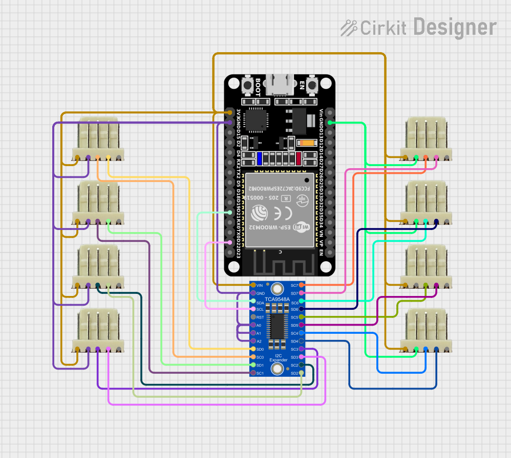
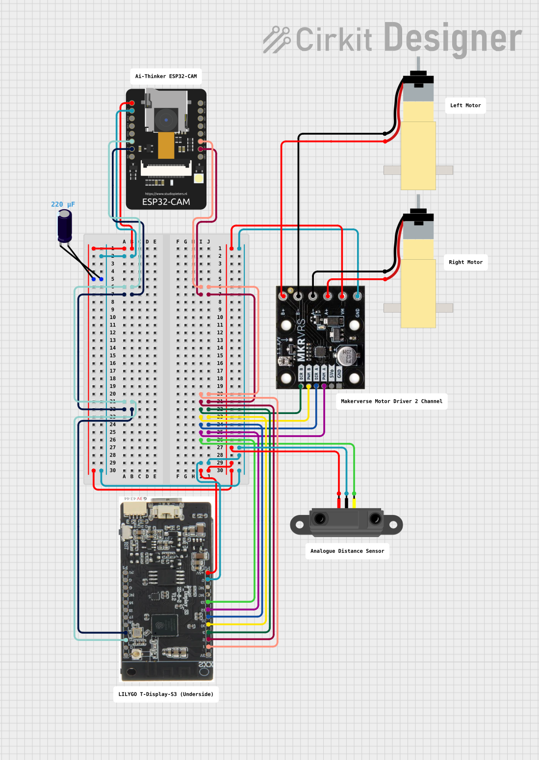
  • Sensor arrays in robotics and IoT applications
  • Multi-display systems
  • Testing and debugging multiple I2C devices

Technical Specifications

Key Technical Details

  • Operating Voltage: 1.65V to 5.5V
  • I2C Address Range: 0x70 to 0x77 (configurable via A0, A1, A2 pins)
  • Maximum I2C Clock Frequency: 400 kHz (Fast Mode)
  • Number of Channels: 8
  • Channel Isolation: Each channel is independently controlled
  • Low Standby Current: 1 µA (typical)
  • Package Type: TSSOP-16 or similar

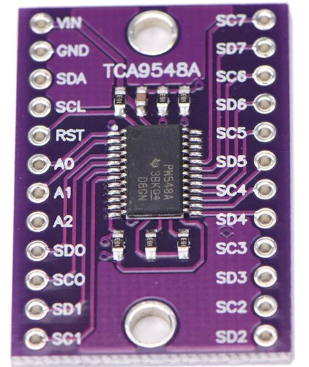
Pin Configuration and Descriptions

The TCA9548A has 16 pins, as described in the table below:

Pin Number Pin Name Description
1 A0 Address selection bit 0 (connect to GND or VCC to set I2C address)
2 A1 Address selection bit 1 (connect to GND or VCC to set I2C address)
3 A2 Address selection bit 2 (connect to GND or VCC to set I2C address)
4 VCC Power supply input (1.65V to 5.5V)
5 SDA I2C data line (connect to master SDA line)
6 SCL I2C clock line (connect to master SCL line)
7 RESET Active-low reset input (pull high for normal operation)
8 GND Ground
9–16 SD0–SD7 I2C data lines for channels 0–7 (connect to slave devices on each channel)

Usage Instructions

How to Use the TCA9548A in a Circuit

  1. Power the TCA9548A: Connect the VCC pin to a power source (1.65V to 5.5V) and the GND pin to ground.
  2. Set the I2C Address: Configure the A0, A1, and A2 pins to set the desired I2C address. These pins can be connected to GND (logic 0) or VCC (logic 1). The default address is 0x70 when all address pins are grounded.
  3. Connect the I2C Master: Attach the SDA and SCL lines of the TCA9548A to the corresponding lines of the I2C master device.
  4. Connect I2C Slaves: Attach the SDA and SCL lines of each slave device to the corresponding SDx pins of the TCA9548A. Each slave device should be connected to a separate channel to avoid address conflicts.
  5. Control the Channels: Use the I2C master to send commands to the TCA9548A to enable or disable specific channels. Only one channel can be active at a time.

Important Considerations and Best Practices

  • Pull-Up Resistors: Ensure that appropriate pull-up resistors are present on the SDA and SCL lines of the master and each active channel. Typically, 4.7 kΩ or 10 kΩ resistors are used.
  • Reset Pin: If the RESET pin is not used, connect it to VCC to ensure normal operation.
  • Channel Switching: Only one channel can be active at a time. Switching between channels is done by writing to the TCA9548A's control register.
  • I2C Address Conflicts: Avoid connecting multiple devices with the same address to the same channel.

Example Code for Arduino UNO

The following example demonstrates how to use the TCA9548A with an Arduino UNO to communicate with a device on channel 0.

#include <Wire.h> // Include the Wire library for I2C communication

#define TCA9548A_ADDRESS 0x70 // Default I2C address of the TCA9548A

// Function to select a specific channel on the TCA9548A
void selectChannel(uint8_t channel) {
  if (channel > 7) return; // Ensure the channel is valid (0-7)
  Wire.beginTransmission(TCA9548A_ADDRESS); // Start communication with TCA9548A
  Wire.write(1 << channel); // Write to control register to enable the channel
  Wire.endTransmission(); // End communication
}

void setup() {
  Wire.begin(); // Initialize I2C communication
  Serial.begin(9600); // Initialize serial communication for debugging

  Serial.println("Selecting channel 0...");
  selectChannel(0); // Enable channel 0
}

void loop() {
  // Example: Communicate with a device on channel 0
  Wire.beginTransmission(0x40); // Replace 0x40 with the I2C address of your device
  Wire.write(0x00); // Example: Write a command or register address
  Wire.endTransmission();

  delay(1000); // Wait for 1 second before repeating
}

Troubleshooting and FAQs

Common Issues and Solutions

  1. No Communication with Slave Devices

    • Cause: Incorrect channel selection or I2C address.
    • Solution: Verify that the correct channel is selected using the control register. Check the I2C address of the slave device.
  2. Multiple Devices Not Responding

    • Cause: Missing or incorrect pull-up resistors.
    • Solution: Ensure that pull-up resistors are present on the SDA and SCL lines of the master and each active channel.
  3. TCA9548A Not Responding

    • Cause: Incorrect I2C address configuration.
    • Solution: Verify the A0, A1, and A2 pin connections and ensure they match the expected address.
  4. Channel Switching Not Working

    • Cause: Incorrect control register value.
    • Solution: Ensure that only one bit is set in the control register to activate a single channel.

FAQs

  • Q: Can multiple channels be active simultaneously?
    A: No, the TCA9548A allows only one channel to be active at a time.

  • Q: What happens if the RESET pin is left floating?
    A: The TCA9548A may not operate correctly. Connect the RESET pin to VCC if it is not used.

  • Q: Can the TCA9548A work with 3.3V and 5V devices simultaneously?
    A: Yes, as long as the voltage levels are compatible and proper pull-up resistors are used.

  • Q: How do I determine the I2C address of the TCA9548A?
    A: The address is determined by the A0, A1, and A2 pin connections. Refer to the datasheet for the address mapping.