
How to Use Molex Picoblade Series Header: Examples, Pinouts, and Specs

 Design with Molex Picoblade Series Header in Cirkit Designer
Introduction
The Molex Picoblade Series Header (Part ID: 0533980271) is a compact, low-profile connector designed for high-density applications. It features a reliable locking mechanism, ensuring secure wire-to-board connections. This connector is widely used in applications where space is limited, such as consumer electronics, medical devices, and industrial equipment. Its robust design and versatility make it a popular choice for engineers and designers.
Explore Projects Built with Molex Picoblade Series Header
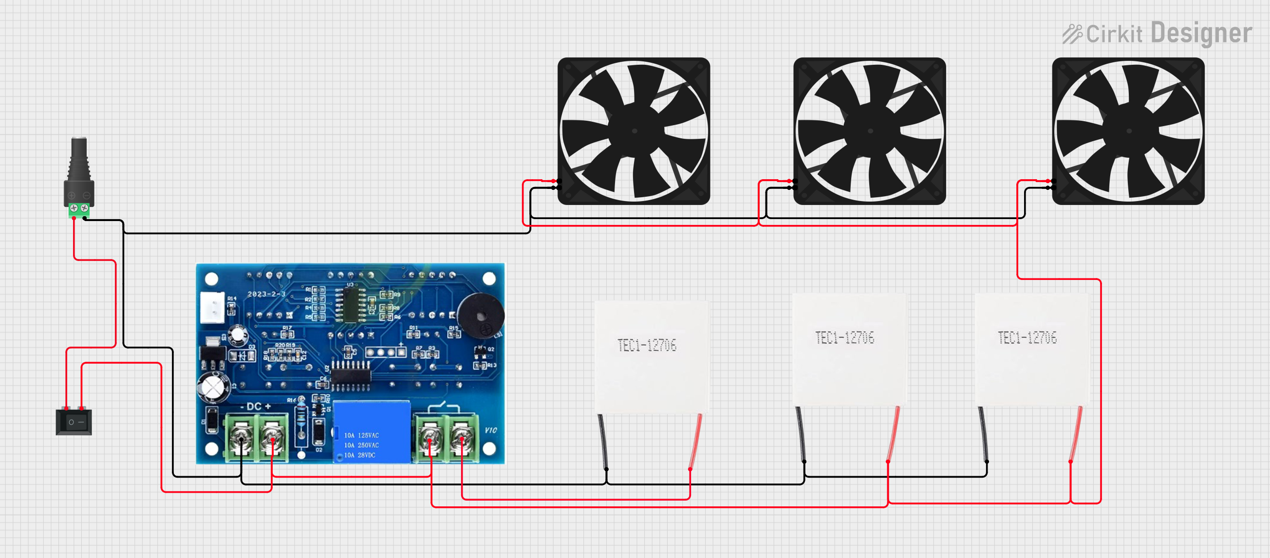 Open Project in Cirkit Designer
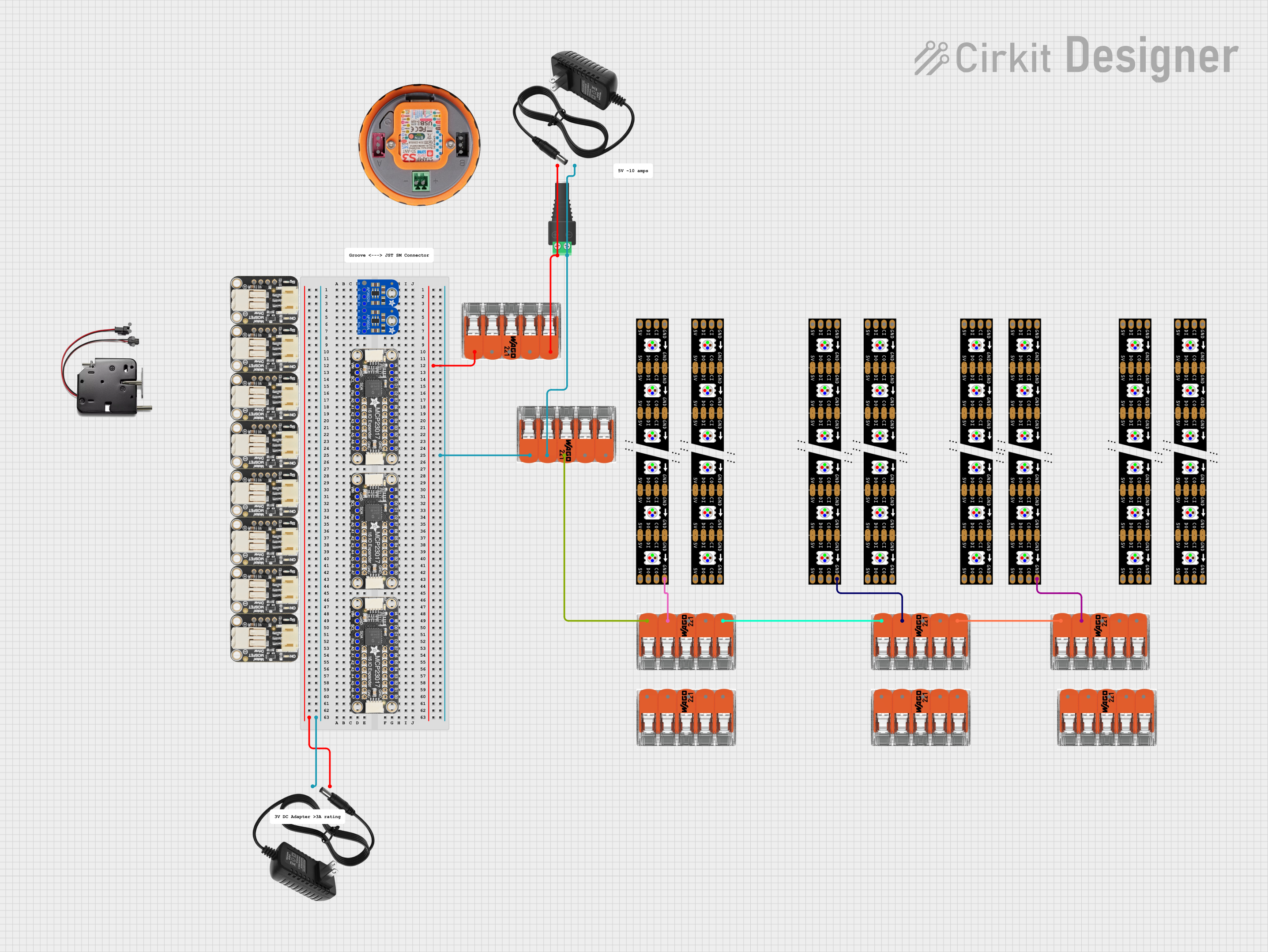 Open Project in Cirkit Designer
 Open Project in Cirkit Designer
 Open Project in Cirkit Designer
Explore Projects Built with Molex Picoblade Series Header
Open Project in Cirkit DesignerOpen Project in Cirkit DesignerOpen Project in Cirkit DesignerOpen Project in Cirkit DesignerCommon Applications
- Consumer electronics (e.g., cameras, wearables)
- Medical devices
- Industrial control systems
- Automotive electronics
- Robotics and IoT devices
Technical Specifications
Key Technical Details
| Parameter | Value |
|---|---|
| Manufacturer | Molex |
| Series | Picoblade |
| Part Number | 0533980271 |
| Connector Type | Wire-to-Board |
| Number of Positions | 2 |
| Pitch | 1.25 mm |
| Mounting Type | Surface Mount (SMT) |
| Current Rating | 1 A per contact |
| Voltage Rating | 125 V AC/DC |
| Operating Temperature | -25°C to +85°C |
| Locking Mechanism | Positive Lock |
| Contact Material | Phosphor Bronze |
| Contact Plating | Tin |
| Housing Material | Nylon (UL 94V-0 rated) |
Pin Configuration and Descriptions
The Molex Picoblade Series Header (0533980271) is a 2-position connector. Below is the pin configuration:
| Pin Number | Description | Notes |
|---|---|---|
| 1 | Signal/Power Line 1 | Can carry signal or power |
| 2 | Signal/Power Line 2 | Can carry signal or power |
Usage Instructions
How to Use the Component in a Circuit
- PCB Design: Ensure your PCB layout includes a 1.25 mm pitch footprint for the header. The Molex Picoblade header is surface-mounted, so solder pads must be designed accordingly.
- Soldering: Use a reflow soldering process for secure mounting. Ensure the solder paste is applied evenly to avoid cold solder joints.
- Mating Connector: Use a compatible Molex Picoblade receptacle or cable assembly for proper connection. Ensure the locking mechanism clicks into place for a secure fit.
- Wiring: When connecting wires to the mating receptacle, use a Molex crimping tool to ensure proper termination of wires to the contacts.
Important Considerations and Best Practices
- Current and Voltage Ratings: Do not exceed the specified current (1 A) and voltage (125 V AC/DC) ratings to avoid overheating or damage.
- Temperature Range: Operate the connector within the specified temperature range (-25°C to +85°C) to ensure reliability.
- Locking Mechanism: Always verify that the locking mechanism is engaged to prevent accidental disconnection.
- Handling: Avoid excessive force when mating or unmating the connector to prevent damage to the contacts or housing.
Example: Connecting to an Arduino UNO
The Molex Picoblade header can be used to connect sensors or other peripherals to an Arduino UNO. Below is an example of how to connect a sensor using the Picoblade header:
Circuit Diagram
- Pin 1: Connect to the sensor's signal output.
- Pin 2: Connect to the Arduino's GND.
Arduino Code Example
// Example code to read data from a sensor connected via the Molex Picoblade header
// Pin 1 of the header is connected to Arduino pin A0 (analog input)
// Pin 2 of the header is connected to Arduino GND

const int sensorPin = A0; // Define the analog pin connected to the sensor

void setup() {
  Serial.begin(9600); // Initialize serial communication at 9600 baud
  pinMode(sensorPin, INPUT); // Set the sensor pin as an input
}

void loop() {
  int sensorValue = analogRead(sensorPin); // Read the sensor value
  Serial.print("Sensor Value: ");
  Serial.println(sensorValue); // Print the sensor value to the Serial Monitor
  delay(500); // Wait for 500 milliseconds before the next reading
}
Troubleshooting and FAQs
Common Issues and Solutions
Loose Connection
- Issue: The connector feels loose or disconnects easily.
- Solution: Ensure the mating connector is fully inserted and the locking mechanism is engaged.
Intermittent Signal
- Issue: The signal is unstable or intermittent.
- Solution: Check for cold solder joints on the PCB. Re-solder if necessary. Verify that the wires are properly crimped to the mating connector.
Overheating
- Issue: The connector becomes hot during operation.
- Solution: Ensure the current and voltage ratings are not exceeded. Check for short circuits in the circuit.
Connector Damage
- Issue: The housing or contacts are damaged.
- Solution: Replace the damaged connector. Avoid excessive force when mating or unmating.
FAQs
Q1: Can the Molex Picoblade header be used in high-vibration environments?
A1: Yes, the positive locking mechanism ensures a secure connection, making it suitable for high-vibration environments.
Q2: What tools are recommended for crimping wires to the mating connector?
A2: Molex recommends using their official crimping tools for optimal results and reliable connections.
Q3: Is the connector RoHS compliant?
A3: Yes, the Molex Picoblade Series Header is RoHS compliant.
Q4: Can this connector handle power and signal simultaneously?
A4: Yes, the connector can handle both power and signal, provided the current and voltage ratings are not exceeded.