How to Use Bridge Rectifier: Examples, Pinouts, and Specs
Introduction
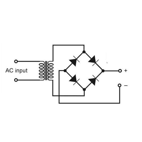
A bridge rectifier is an electronic component that is essential in converting alternating current (AC) to direct current (DC). It consists of four diodes arranged in a bridge configuration to provide full-wave rectification. This is crucial for applications that require a steady DC voltage, such as in power supplies for electronic devices, battery charging systems, and DC motor drives.
Explore Projects Built with Bridge Rectifier
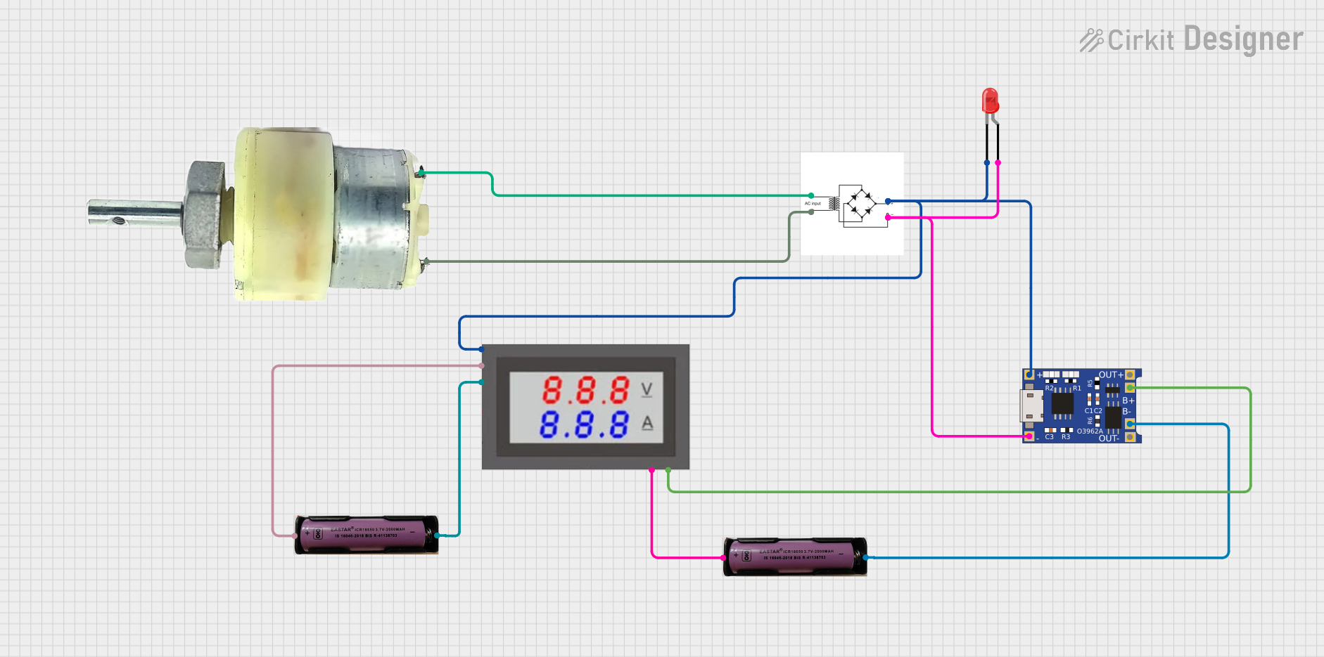
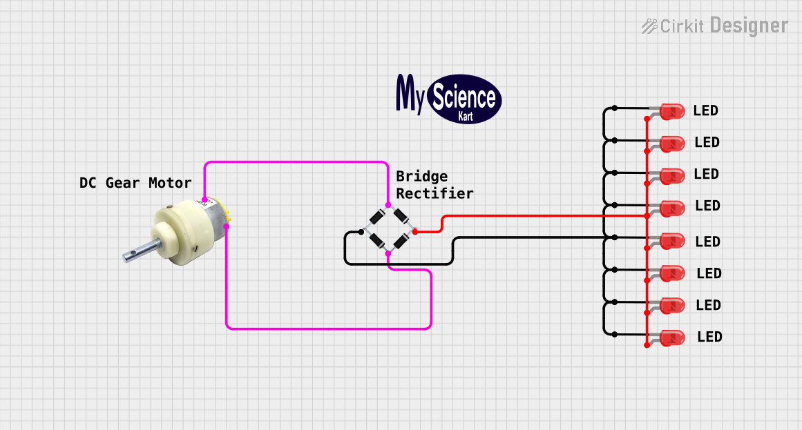
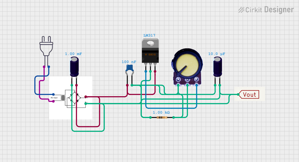
Explore Projects Built with Bridge Rectifier
Common Applications and Use Cases
- Power supplies for electronic circuits
- Battery charging systems
- DC motor control circuits
- Signal demodulation
- Power conversion systems for renewable energy sources
Technical Specifications
Key Technical Details
- Maximum Repetitive Reverse Voltage (Vrrm): The maximum peak reverse voltage the diode can withstand.
- Average Forward Current (If(AV)): The maximum average current the diodes can conduct.
- Forward Surge Current (Ifsm): The maximum current the diode can conduct in a surge condition.
- Operating Junction Temperature (Tj): The temperature range over which the diode can operate without damage.
Pin Configuration and Descriptions
| Pin | Description |
|---|---|
| AC1 | First alternating current input |
| AC2 | Second alternating current input |
| + | Positive direct current output |
| - | Negative direct current output |
Usage Instructions
How to Use the Component in a Circuit
- Connect the AC inputs (AC1 and AC2) to the transformer's secondary winding.
- Connect the positive DC output (+) to the positive rail of the circuit.
- Connect the negative DC output (-) to the ground rail of the circuit.
- Add a smoothing capacitor across the DC output to reduce voltage ripple.
Important Considerations and Best Practices
- Ensure the bridge rectifier's voltage and current ratings exceed the circuit's requirements.
- Use a heat sink if the rectifier is expected to handle high power levels to prevent overheating.
- Place a fuse before the AC input for safety against overcurrent conditions.
- The smoothing capacitor should be chosen based on the load's current draw and desired ripple voltage.
Troubleshooting and FAQs
Common Issues Users Might Face
- Excessive Voltage Ripple: This can be due to an inadequate smoothing capacitor or a heavy load that exceeds the rectifier's capacity.
- Overheating: Caused by high current flow without proper heat sinking or by operating the rectifier above its rated temperature.
- Unexpected Voltage Drops: This can occur if the diodes are not matched or if one or more diodes have failed.
Solutions and Tips for Troubleshooting
- If experiencing excessive voltage ripple, increase the capacitance of the smoothing capacitor or reduce the load.
- Attach a heat sink to the rectifier to manage overheating and ensure adequate air flow around the component.
- Check each diode individually with a multimeter to ensure they are functioning correctly. Replace any faulty diodes.
FAQs
Q: Can I use a bridge rectifier to convert DC to AC? A: No, a bridge rectifier is designed for AC to DC conversion only.
Q: How do I choose the right bridge rectifier for my application? A: Consider the maximum voltage and current your application requires and select a rectifier with ratings that exceed these values.
Q: What is the purpose of the smoothing capacitor? A: The smoothing capacitor reduces the ripple in the DC output from the rectifier, providing a more stable DC voltage.
Example Code for Arduino UNO
The following example demonstrates how to use a bridge rectifier with an Arduino UNO to power the board with an AC source.
// No specific code is required for the bridge rectifier itself, as it is a passive component.
// However, the following code can be used to monitor the DC voltage output from the rectifier.

const int analogInputPin = A0; // Connect this pin to the DC output through a voltage divider

void setup() {
  Serial.begin(9600);
}

void loop() {
  int sensorValue = analogRead(analogInputPin); // Read the analog input
  float voltage = sensorValue * (5.0 / 1023.0); // Convert to voltage
  Serial.print("DC Voltage: ");
  Serial.println(voltage);
  delay(1000); // Wait for a second before the next read
}
Note: When connecting the DC output to the Arduino, ensure that the voltage does not exceed the board's maximum voltage rating. Use a voltage divider or a regulator if necessary.