How to Use ESP32 ESP-WROOM-32: Examples, Pinouts, and Specs
Introduction
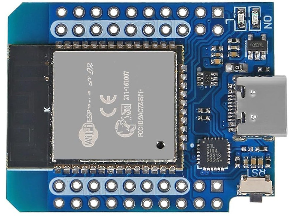
The ESP32 ESP-WROOM-32 is a versatile microcontroller module manufactured by ACEIRMC (Part ID: D1 Mini Type-C). It is equipped with integrated Wi-Fi and Bluetooth capabilities, making it a popular choice for Internet of Things (IoT) applications. This module features a dual-core processor, a wide range of GPIO pins, and support for multiple communication protocols, enabling developers to create smart devices, wireless systems, and automation projects with ease.
Explore Projects Built with ESP32 ESP-WROOM-32


Explore Projects Built with ESP32 ESP-WROOM-32
Common Applications and Use Cases
- Smart home devices (e.g., smart lights, thermostats, and security systems)
- IoT sensors and data loggers
- Wireless communication hubs
- Robotics and automation systems
- Wearable devices
- Prototyping and educational projects
Technical Specifications
The following table outlines the key technical details of the ESP32 ESP-WROOM-32 module:
| Parameter | Specification |
|---|---|
| Microcontroller | Tensilica Xtensa LX6 Dual-Core Processor |
| Clock Speed | Up to 240 MHz |
| Flash Memory | 4 MB (varies by model) |
| SRAM | 520 KB |
| Wi-Fi Standard | 802.11 b/g/n (2.4 GHz) |
| Bluetooth | Bluetooth v4.2 BR/EDR and BLE |
| Operating Voltage | 3.3V |
| Input Voltage Range | 5V (via USB Type-C) or 3.3V (via VIN pin) |
| GPIO Pins | 34 (multipurpose, including ADC, DAC, PWM, I2C, SPI, UART) |
| ADC Resolution | 12-bit |
| DAC Resolution | 8-bit |
| Power Consumption | Ultra-low power consumption in deep sleep mode (as low as 10 µA) |
| Operating Temperature | -40°C to +85°C |
| Dimensions | 25.5 mm x 18 mm |
Pin Configuration and Descriptions
The ESP32 ESP-WROOM-32 module features a variety of pins for different functionalities. Below is a table summarizing the key pins and their descriptions:
| Pin Name | Type | Description |
|---|---|---|
| VIN | Power Input | Input voltage (5V) when powered via USB Type-C or external power source. |
| 3V3 | Power Output | Regulated 3.3V output for powering external components. |
| GND | Ground | Ground connection. |
| EN | Enable | Enables or disables the module. Active high. |
| GPIO0-GPIO39 | GPIO | General-purpose input/output pins. Multipurpose (ADC, DAC, PWM, I2C, SPI, etc.). |
| TXD0, RXD0 | UART | Default UART pins for serial communication. |
| ADC1, ADC2 | Analog Input | 12-bit ADC channels for analog-to-digital conversion. |
| DAC1, DAC2 | Analog Output | 8-bit DAC channels for digital-to-analog conversion. |
| SCL, SDA | I2C | I2C clock (SCL) and data (SDA) pins. |
| MOSI, MISO, SCK, CS | SPI | SPI communication pins (Master Out Slave In, Master In Slave Out, Clock, Chip Select). |
Usage Instructions
How to Use the ESP32 ESP-WROOM-32 in a Circuit
Powering the Module:
- Use a USB Type-C cable to supply 5V to the module. Alternatively, provide 3.3V directly to the VIN pin.
- Ensure the power source can supply sufficient current (at least 500 mA) for stable operation.
Connecting GPIO Pins:
- Configure GPIO pins as input or output based on your application.
- Use pull-up or pull-down resistors for input pins to avoid floating states.
Programming the Module:
- Install the ESP32 board package in the Arduino IDE or use the ESP-IDF development framework.
- Connect the module to your computer via USB Type-C and select the appropriate COM port in the IDE.
- Write and upload your code to the module.
Communication Protocols:
- Use I2C, SPI, or UART for interfacing with sensors, displays, or other peripherals.
- Configure the pins and communication settings in your code.
Important Considerations and Best Practices
- Voltage Levels: Ensure all connected peripherals operate at 3.3V logic levels to avoid damaging the module.
- Deep Sleep Mode: Use deep sleep mode to conserve power in battery-powered applications.
- Antenna Placement: Avoid placing metal objects near the onboard antenna to ensure optimal Wi-Fi and Bluetooth performance.
- Boot Mode: To enter bootloader mode, hold the BOOT button while pressing the EN (reset) button.
Example Code for Arduino UNO Integration
Below is an example of using the ESP32 ESP-WROOM-32 to control an LED via Wi-Fi:
#include <WiFi.h>

// Replace with your network credentials
const char* ssid = "Your_SSID";
const char* password = "Your_PASSWORD";

void setup() {
  // Initialize serial communication
  Serial.begin(115200);

  // Connect to Wi-Fi
  Serial.print("Connecting to Wi-Fi");
  WiFi.begin(ssid, password);
  while (WiFi.status() != WL_CONNECTED) {
    delay(500);
    Serial.print(".");
  }
  Serial.println("\nWi-Fi connected!");
}

void loop() {
  // Example: Blink an LED connected to GPIO2
  pinMode(2, OUTPUT); // Set GPIO2 as output
  digitalWrite(2, HIGH); // Turn LED on
  delay(1000); // Wait 1 second
  digitalWrite(2, LOW); // Turn LED off
  delay(1000); // Wait 1 second
}
Troubleshooting and FAQs
Common Issues and Solutions
Module Not Detected by Computer:
- Ensure the USB Type-C cable is data-capable (not just for charging).
- Check if the correct COM port is selected in the IDE.
Wi-Fi Connection Fails:
- Verify the SSID and password in your code.
- Ensure the Wi-Fi network operates on the 2.4 GHz band (not 5 GHz).
GPIO Pin Malfunction:
- Check for incorrect pin configurations in your code.
- Avoid using reserved pins (e.g., GPIO6-GPIO11 are used for flash memory).
Overheating:
- Ensure the module is not drawing excessive current.
- Use proper heat dissipation methods if the module operates in high-temperature environments.
FAQs
Q: Can the ESP32 ESP-WROOM-32 operate on battery power?
A: Yes, the module can be powered by a 3.7V LiPo battery with a suitable voltage regulator to provide 3.3V.
Q: How do I reset the module?
A: Press the EN (reset) button to restart the module.
Q: Can I use the ESP32 with a 5V logic device?
A: No, the ESP32 operates at 3.3V logic levels. Use a level shifter for compatibility with 5V devices.