How to Use Uh-oh Battery Level Indicator Kit: Examples, Pinouts, and Specs
Introduction
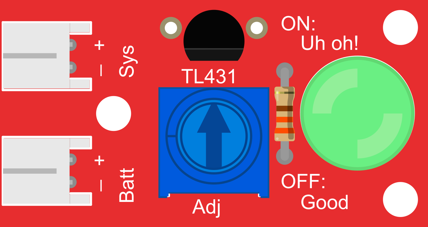
The Uh-oh Battery Level Indicator Kit is an educational and practical tool designed for electronics enthusiasts and hobbyists. This DIY kit enables users to construct a simple yet effective battery level indicator circuit, which uses a series of LEDs to visually represent the remaining charge in a battery. It is particularly useful for portable projects where monitoring battery life is crucial.
Explore Projects Built with Uh-oh Battery Level Indicator Kit


Explore Projects Built with Uh-oh Battery Level Indicator Kit
Common Applications and Use Cases
- Portable electronic devices
- DIY electronics projects
- Educational purposes for learning about voltage thresholds and LED indicators
- Remote controls, flashlights, and other battery-operated gadgets
Technical Specifications
Key Technical Details
- Operating Voltage Range: Typically 3V to 4.5V
- Current Consumption: Dependent on the number of LEDs lit
- Power Ratings: Minimal, as it is designed to consume low power to avoid significant battery drain
- Indicator Levels: Typically 3 to 5 LEDs indicating various charge levels
Pin Configuration and Descriptions
| Pin Number | Description |
|---|---|
| 1 | Ground (GND) |
| 2 | Voltage Input (VIN) |
| 3 | LED 1 Output (Highest Level) |
| 4 | LED 2 Output |
| 5 | LED 3 Output |
| 6 | LED 4 Output (Lowest Level) |
Usage Instructions
How to Use the Component in a Circuit
- Assembly: Follow the provided instructions to assemble the kit. Solder the components onto the provided PCB, ensuring correct orientation and secure connections.
- Connection: Connect the ground pin to the negative terminal of your battery and the voltage input pin to the positive terminal.
- Mounting LEDs: Place the LEDs in a visible location on your project, ensuring they are correctly oriented (long leg to positive).
- Testing: Once connected, the LEDs should light up corresponding to the battery's voltage level.
Important Considerations and Best Practices
- Voltage Calibration: Ensure that the voltage thresholds for each LED are correctly set for your specific battery type.
- Power Consumption: To conserve battery life, consider using high-efficiency LEDs.
- Protection: Use a current-limiting resistor with each LED to prevent damage.
- Isolation: If integrating into a larger circuit, ensure that the indicator circuit is isolated from high-current paths.
Example Code for Arduino UNO
// Uh-oh Battery Level Indicator Kit - Example Arduino Code
// Connect the Uh-oh Battery Level Indicator's VIN to an analog pin for monitoring

const int batteryPin = A0; // Analog pin connected to Uh-oh Battery Level Indicator VIN
const int ledPins[] = {3, 4, 5, 6}; // Digital pins connected to the LED outputs

void setup() {
  // Initialize the LED pins as outputs
  for (int i = 0; i < sizeof(ledPins)/sizeof(ledPins[0]); i++) {
    pinMode(ledPins[i], OUTPUT);
  }
}

void loop() {
  // Read the battery level from the Uh-oh Battery Level Indicator
  int batteryLevel = analogRead(batteryPin);

  // Turn on the appropriate number of LEDs based on the battery level
  for (int i = 0; i < sizeof(ledPins)/sizeof(ledPins[0]); i++) {
    if (batteryLevel > i * 1023 / sizeof(ledPins)/sizeof(ledPins[0])) {
      digitalWrite(ledPins[i], HIGH); // Turn on the LED
    } else {
      digitalWrite(ledPins[i], LOW); // Turn off the LED
    }
  }

  // Delay for a bit before reading the battery level again
  delay(1000);
}
Troubleshooting and FAQs
Common Issues Users Might Face
- LEDs Not Lighting Up: Ensure all connections are secure and the battery is charged.
- Incorrect LED Indication: Verify that the voltage thresholds are correctly set for your battery type.
- LEDs Always On/Off: Check for short circuits or miswiring in your assembly.
Solutions and Tips for Troubleshooting
- Double-Check Assembly: Revisit the kit instructions and ensure all components are correctly placed and soldered.
- Battery Check: Use a multimeter to confirm the battery's voltage and compare it with the indicator's thresholds.
- Resistor Values: Confirm that the current-limiting resistors are of the correct value for your LEDs.
FAQs
Q: Can I use the Uh-oh Battery Level Indicator Kit with a rechargeable battery? A: Yes, but ensure that the voltage thresholds are appropriate for the rechargeable battery's chemistry.
Q: How can I adjust the voltage thresholds for each LED? A: The kit typically includes a method to adjust thresholds, such as variable resistors or a programmable component. Refer to the specific kit instructions for details.
Q: Is it possible to use more or fewer LEDs for different battery levels? A: Yes, the kit can be modified to use a different number of LEDs, but this may require changes to the circuit design and calibration.
Remember, this documentation is a starting point. Always refer to the specific instructions and data sheets provided with your Uh-oh Battery Level Indicator Kit for the most accurate and detailed information.