How to Use Sparkfun Babybuck 3.3v: Examples, Pinouts, and Specs
Introduction
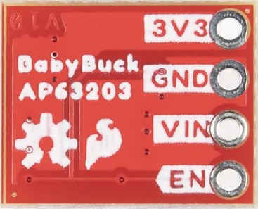
The SparkFun BabyBuck 3.3V (Manufacturer Part ID: AP63203) is a compact DC-DC buck converter designed to step down higher input voltages to a stable 3.3V output. This component is ideal for powering low-voltage devices such as microcontrollers, sensors, and other electronics from higher voltage sources like batteries or power supplies. Its small form factor and high efficiency make it a versatile choice for embedded systems and portable applications.
Explore Projects Built with Sparkfun Babybuck 3.3v
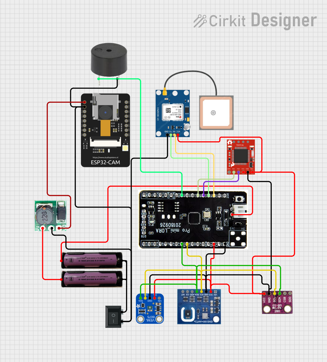


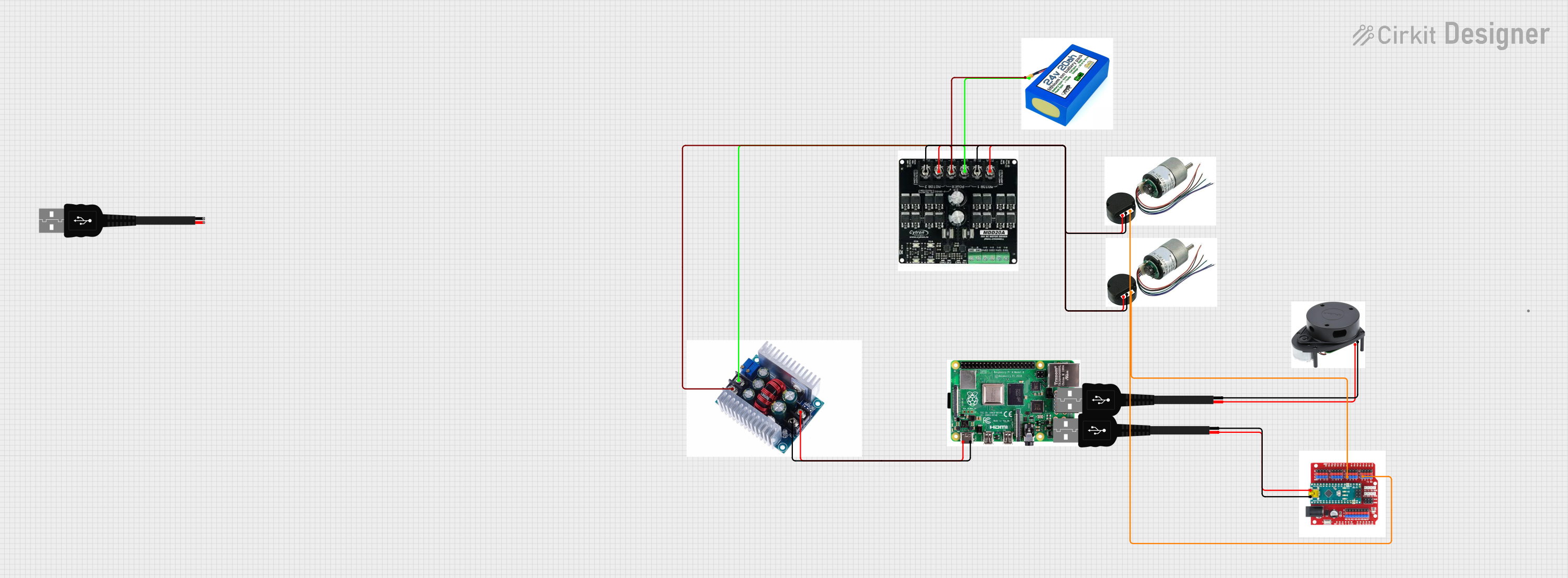
Explore Projects Built with Sparkfun Babybuck 3.3v
Common Applications and Use Cases
- Powering 3.3V microcontrollers (e.g., ESP32, Arduino Pro Mini 3.3V)
- Supplying power to low-voltage sensors and modules
- Battery-powered devices requiring efficient voltage regulation
- Prototyping and development boards
Technical Specifications
The following table outlines the key technical details of the SparkFun BabyBuck 3.3V:
| Parameter | Value |
|---|---|
| Input Voltage Range | 3.8V to 32V |
| Output Voltage | 3.3V (fixed) |
| Output Current | Up to 2A |
| Efficiency | Up to 95% |
| Switching Frequency | 1.1 MHz |
| Operating Temperature | -40°C to +125°C |
| Dimensions | 10.4mm x 10.4mm x 4.1mm |
Pin Configuration and Descriptions
The SparkFun BabyBuck 3.3V has the following pinout:
| Pin Name | Description |
|---|---|
| VIN | Input voltage pin. Connect to the higher voltage source (3.8V to 32V). |
| GND | Ground pin. Connect to the ground of the circuit. |
| VOUT | Output voltage pin. Provides a regulated 3.3V output. |
| EN | Enable pin. Pull high to enable the converter; pull low to disable it. |
Usage Instructions
How to Use the Component in a Circuit
Connect the Input Voltage (VIN):
Attach the VIN pin to a power source with a voltage between 3.8V and 32V. Ensure the input voltage is within this range to avoid damaging the component.Connect the Ground (GND):
Connect the GND pin to the ground of your circuit.Connect the Output Voltage (VOUT):
Attach the VOUT pin to the device or circuit that requires a 3.3V power supply.Enable the Converter (Optional):
If you wish to control the BabyBuck's operation, connect the EN pin to a microcontroller or a pull-up resistor. Pull the EN pin high (to VIN) to enable the converter or low (to GND) to disable it.
Important Considerations and Best Practices
- Input Voltage Range: Ensure the input voltage is within the specified range (3.8V to 32V). Exceeding this range can damage the component.
- Output Current Limit: The BabyBuck can supply up to 2A of current. Do not exceed this limit to prevent overheating or failure.
- Thermal Management: While the BabyBuck is highly efficient, ensure adequate ventilation or heat dissipation if operating near the maximum current limit.
- Bypass Capacitors: Use appropriate input and output capacitors (as recommended in the AP63203 datasheet) to ensure stable operation and minimize noise.
Example: Using BabyBuck 3.3V with an Arduino UNO
Although the Arduino UNO operates at 5V, you can use the BabyBuck to power 3.3V peripherals connected to the Arduino. Below is an example of how to use the BabyBuck to power a 3.3V sensor:
// Example: Reading data from a 3.3V sensor using Arduino UNO
// Connect the BabyBuck's VOUT to the sensor's VCC pin
// Connect the BabyBuck's GND to the sensor's GND pin

const int sensorPin = A0; // Analog pin connected to the sensor output

void setup() {
  Serial.begin(9600); // Initialize serial communication
  pinMode(sensorPin, INPUT); // Set the sensor pin as input
}

void loop() {
  int sensorValue = analogRead(sensorPin); // Read the sensor value
  float voltage = sensorValue * (3.3 / 1023.0); // Convert to voltage (3.3V reference)

  // Print the sensor voltage to the Serial Monitor
  Serial.print("Sensor Voltage: ");
  Serial.print(voltage);
  Serial.println(" V");

  delay(1000); // Wait for 1 second before the next reading
}
Troubleshooting and FAQs
Common Issues and Solutions
No Output Voltage:
- Cause: The EN pin is not connected or is pulled low.
- Solution: Ensure the EN pin is pulled high (to VIN) to enable the converter.
Overheating:
- Cause: Exceeding the maximum output current (2A) or poor ventilation.
- Solution: Reduce the load current or improve heat dissipation by adding a heatsink or increasing airflow.
Output Voltage Instability:
- Cause: Insufficient input or output capacitors.
- Solution: Add capacitors as recommended in the AP63203 datasheet (e.g., 10µF ceramic capacitors on both input and output).
Noisy Output:
- Cause: High-frequency noise due to switching.
- Solution: Use low-ESR capacitors and ensure proper grounding in the circuit.
FAQs
Q: Can the BabyBuck 3.3V be used with a 12V battery?
A: Yes, the BabyBuck can step down a 12V input to a stable 3.3V output, as long as the input voltage is within the 3.8V to 32V range.
Q: Is the BabyBuck suitable for powering an ESP32?
A: Yes, the BabyBuck can provide a stable 3.3V output with up to 2A of current, which is sufficient for most ESP32 applications.
Q: Can I use the BabyBuck to power multiple devices?
A: Yes, as long as the total current draw of all devices does not exceed 2A.
Q: What happens if the input voltage drops below 3.8V?
A: The BabyBuck may stop regulating properly, and the output voltage may become unstable or drop below 3.3V.
By following these guidelines and best practices, you can effectively integrate the SparkFun BabyBuck 3.3V into your projects for reliable and efficient voltage regulation.