How to Use Esp32-S3-Zero: Examples, Pinouts, and Specs
Introduction
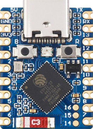
The ESP32-S3-Zero by Waveshare (Part ID: S3) is a low-power, dual-core microcontroller designed for IoT applications. It integrates both Wi-Fi and Bluetooth capabilities, making it a versatile choice for wireless communication projects. With its rich set of peripherals, including GPIO, ADC, PWM, and more, the ESP32-S3-Zero is ideal for applications such as smart home devices, wearables, industrial automation, and sensor networks.
Explore Projects Built with Esp32-S3-Zero


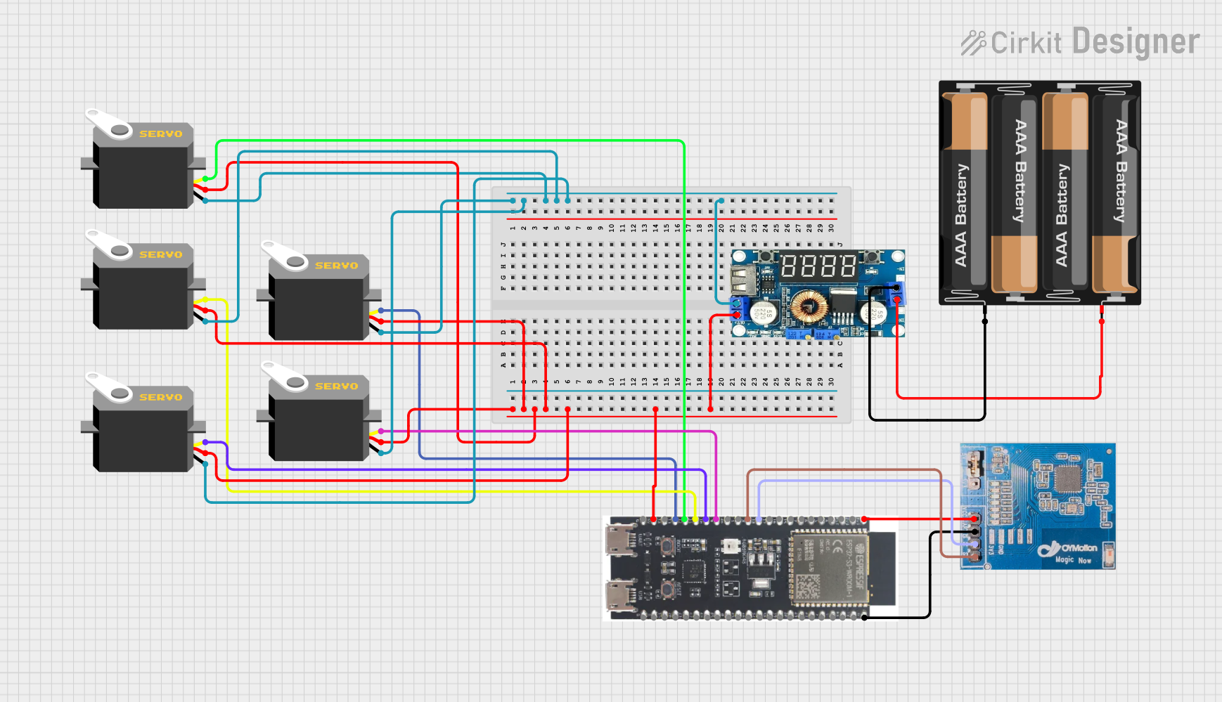

Explore Projects Built with Esp32-S3-Zero
Common Applications:
- IoT Devices: Smart home automation, environmental monitoring, and connected appliances.
- Wearables: Fitness trackers, health monitoring devices, and smart watches.
- Industrial Automation: Remote monitoring, control systems, and data logging.
- Prototyping: Rapid development of wireless communication and sensor-based projects.
Technical Specifications
Key Technical Details:
| Parameter | Value |
|---|---|
| Microcontroller | ESP32-S3 (dual-core Xtensa LX7) |
| Clock Speed | Up to 240 MHz |
| Flash Memory | 8 MB (external) |
| RAM | 512 KB SRAM + 2 MB PSRAM |
| Wi-Fi | 802.11 b/g/n (2.4 GHz) |
| Bluetooth | Bluetooth 5.0 (LE) |
| GPIO Pins | 21 (configurable for various functions) |
| ADC Channels | 12-bit ADC, up to 20 channels |
| PWM Channels | Up to 16 channels |
| Communication Interfaces | UART, SPI, I2C, I2S, CAN, USB-OTG |
| Operating Voltage | 3.3V |
| Power Consumption | Ultra-low power modes available (deep sleep current: ~10 µA) |
| Dimensions | 25 mm x 50 mm |
Pin Configuration and Descriptions:
| Pin Name | Type | Description |
|---|---|---|
| 3V3 | Power | 3.3V power input/output |
| GND | Power | Ground connection |
| GPIO0 | Digital I/O | General-purpose I/O, boot mode selection |
| GPIO1-21 | Digital I/O | Configurable as input/output, ADC, PWM, or other peripherals |
| TXD0 | UART TX | UART0 transmit pin |
| RXD0 | UART RX | UART0 receive pin |
| EN | Reset | Reset pin for the microcontroller |
| USB D+ | USB Data | USB data positive line |
| USB D- | USB Data | USB data negative line |
Usage Instructions
How to Use the ESP32-S3-Zero in a Circuit:
Powering the Board:
- Supply 3.3V to the
3V3pin and connectGNDto ground. - Alternatively, power the board via the USB port for development purposes.
- Supply 3.3V to the
Programming the Board:
- Use the USB-OTG interface to connect the ESP32-S3-Zero to your computer.
- Install the necessary drivers and development tools (e.g., Arduino IDE or ESP-IDF).
- Select the correct board and port in your development environment.
Connecting Peripherals:
- Use the GPIO pins for digital input/output, ADC for analog signals, and PWM for motor control or LED dimming.
- Ensure proper voltage levels for connected peripherals (3.3V logic).
Wireless Communication:
- Configure Wi-Fi and Bluetooth settings in your code to enable wireless communication.
Important Considerations and Best Practices:
- Voltage Levels: Ensure all connected peripherals operate at 3.3V logic to avoid damage.
- Power Supply: Use a stable power source to prevent unexpected resets or malfunctions.
- Pin Multiplexing: Many pins have multiple functions; configure them appropriately in your code.
- Antenna Placement: For optimal wireless performance, avoid placing metal objects near the onboard antenna.
Example Code for Arduino UNO Integration:
Below is an example of using the ESP32-S3-Zero to connect to a Wi-Fi network and send data to a server:
#include <WiFi.h> // Include the Wi-Fi library

// Replace with your network credentials
const char* ssid = "Your_SSID";
const char* password = "Your_PASSWORD";

void setup() {
  Serial.begin(115200); // Initialize serial communication
  delay(1000);

  // Connect to Wi-Fi
  Serial.print("Connecting to Wi-Fi");
  WiFi.begin(ssid, password);
  while (WiFi.status() != WL_CONNECTED) {
    delay(500);
    Serial.print(".");
  }
  Serial.println("\nWi-Fi connected!");
  Serial.print("IP Address: ");
  Serial.println(WiFi.localIP()); // Print the device's IP address
}

void loop() {
  // Example: Send data to a server (replace with your server details)
  WiFiClient client;
  const char* server = "example.com";
  if (client.connect(server, 80)) {
    client.println("GET / HTTP/1.1");
    client.println("Host: example.com");
    client.println("Connection: close");
    client.println();
  }
  delay(10000); // Wait 10 seconds before sending the next request
}
Troubleshooting and FAQs
Common Issues and Solutions:
The board does not power on:
- Ensure the power supply provides a stable 3.3V.
- Check the USB cable and port if powering via USB.
Unable to upload code:
- Verify that the correct board and port are selected in the development environment.
- Press and hold the
ENbutton while uploading to enter bootloader mode.
Wi-Fi connection fails:
- Double-check the SSID and password in your code.
- Ensure the Wi-Fi network is within range and operational.
GPIO pins not working as expected:
- Confirm the pin configuration in your code matches the intended functionality.
- Check for conflicts if multiple peripherals are using the same pins.
Tips for Troubleshooting:
- Use the serial monitor to debug and view error messages.
- Test the board with a simple "blink" program to verify basic functionality.
- Refer to the ESP32-S3 datasheet for detailed information on pin functions and electrical characteristics.
This documentation provides a comprehensive guide to using the ESP32-S3-Zero microcontroller. Whether you're a beginner or an experienced developer, the ESP32-S3-Zero offers a powerful platform for your IoT and embedded system projects.